China Hot selling Spare Parts for Mower Tiller Pto Drive Shaft (04B-1000) with Free Design Custom

Product Description

Specifications
1.; Use for farm tillers and mower
2.; Assembling with kinds cultivators and tractors
3.; With CE certificate
4.; With some stock
Agriculture Cardan plastic guard tractor PTO shaft

1);Material:; Spring steel,; 65Mn,; 60Si2Mn (Sup6);,; 28SiMnB
2);Process:; Forged
3);Heat treatment:; Normalized-hardened and tempered
4);Hardness:; 40 - 50HRC
5);Working hours:; 200-250 hrs.;

Trade Terms
1.; Trade terms:; FOB,; CIF,; EXW
2.; Sample Policy:; You can test the quality of our sample firstly before you purchase them in mass quantity.;
3.; MOQ:; 1 set
4.; Payment Way:; T/T,; L/C,; Western Union,; D/P.;
5.; Delivery Date:; 10-30 days after deposit paid.; It depends on your order quantity.;
6.; Shipping Way:; By Sea or By Air.;
7.; After Service:; 14 months guarantee of the main parts,; we will send the guarantee parts together with the machine in your next order or we can send them by air express if you need them urgently.;

Company Overview
HangZhou LEFA Industry & Trade Co.;,; Ltd.;,; is a professional manufacturer and exporter of whole set of farm machines and garden tools for 11 years,; mainly including mowers,; tillers,; plows and Japanese tractor parts,; etc.;

We sincerely welcome customers abroad to visit us to discuss cooperation and seek common development.; We believe our company is your most reliable partner and friend!

Code Description
13001  PTO cardan:; 04B-LF-800 
13002  PTO cardan:;05B-LF-800 
13003  PTO cardan:; 04B-LF-1000 
13004  PTO cardan:; 04B-LF-1400 
13005  PTO cardan:; 571B-800 
13006  PTO cardan:; 035B-800 
13007  PTO cardan:; 04B-1000 
13008  PTO cardan:; 04B-RLP-800 
13009 ratchet wheel  
16001 Wheel rim 3.;00-10"(400-10 
16002 Wheel rim 3.;00-12"( 500-12); 4 hole(70*100);
16003 Wheel rim 3.;00-12"( 500-12); 6 hole (90*120);
16004 Wheel rim  5.;5F-16"(7.;50-16 
16005 Wheel rim 3.;00-12"( 500-12); 4 hole(80*120); for YM1401
17001 Roll bar  B 1702   
17002 Roll bar   B 1500 
17003 Roll bar   YM 1401 
17004 Roll bar   YM F14/16  
17005 Roll bar   TU 1700  
17006 Roll bar   B1-15(B1502 ,;B1600); 


How to Replace the Drive Shaft

Several different functions in a vehicle are critical to its functioning, but the driveshaft is probably the part that needs to be understood the most. A damaged or damaged driveshaft can damage many other auto parts. This article will explain how this component works and some of the signs that it may need repair. This article is for the average person who wants to fix their car on their own but may not be familiar with mechanical repairs or even driveshaft mechanics. You can click the link below for more information.
air-compressor

Repair damaged driveshafts

If you own a car, you should know that the driveshaft is an integral part of the vehicle's driveline. They ensure efficient transmission of power from the engine to the wheels and drive. However, if your driveshaft is damaged or cracked, your vehicle will not function properly. To keep your car safe and running at peak efficiency, you should have it repaired as soon as possible. Here are some simple steps to replace the drive shaft.
First, diagnose the cause of the drive shaft damage. If your car is making unusual noises, the driveshaft may be damaged. This is because worn bushings and bearings support the drive shaft. Therefore, the rotation of the drive shaft is affected. The noise will be squeaks, dings or rattles. Once the problem has been diagnosed, it is time to repair the damaged drive shaft.
Professionals can repair your driveshaft at relatively low cost. Costs vary depending on the type of drive shaft and its condition. Axle repairs can range from $300 to $1,000. Labor is usually only around $200. A simple repair can cost between $150 and $1700. You'll save hundreds of dollars if you're able to fix the problem yourself. You may need to spend a few more hours educating yourself about the problem before handing it over to a professional for proper diagnosis and repair.
The cost of repairing a damaged driveshaft varies by model and manufacturer. It can cost as much as $2,000 depending on parts and labor. While labor costs can vary, parts and labor are typically around $70. On average, a damaged driveshaft repair costs between $400 and $600. However, these parts can be more expensive than that. If you don't want to spend money on unnecessarily expensive repairs, you may need to pay a little more.
air-compressor

Learn how drive shafts work

While a car engine may be 1 of the most complex components in your vehicle, the driveshaft has an equally important job. The driveshaft transmits the power of the engine to the wheels, turning the wheels and making the vehicle move. Driveshaft torque refers to the force associated with rotational motion. Drive shafts must be able to withstand extreme conditions or they may break. Driveshafts are not designed to bend, so understanding how they work is critical to the proper functioning of the vehicle.
The drive shaft includes many components. The CV connector is 1 of them. This is the last stop before the wheels spin. CV joints are also known as "doughnut" joints. The CV joint helps balance the load on the driveshaft, the final stop between the engine and the final drive assembly. Finally, the axle is a single rotating shaft that transmits power from the final drive assembly to the wheels.
Different types of drive shafts have different numbers of joints. They transmit torque from the engine to the wheels and must accommodate differences in length and angle. The drive shaft of a front-wheel drive vehicle usually includes a connecting shaft, an inner constant velocity joint and an outer fixed joint. They also have anti-lock system rings and torsional dampers to help them run smoothly. This guide will help you understand the basics of driveshafts and keep your car in good shape.
The CV joint is the heart of the driveshaft, it enables the wheels of the car to move at a constant speed. The connector also helps transmit power efficiently. You can learn more about CV joint driveshafts by looking at the top 3 driveshaft questions
The U-joint on the intermediate shaft may be worn or damaged. Small deviations in these joints can cause slight vibrations and wobble. Over time, these vibrations can wear out drivetrain components, including U-joints and differential seals. Additional wear on the center support bearing is also expected. If your driveshaft is leaking oil, the next step is to check your transmission.
The drive shaft is an important part of the car. They transmit power from the engine to the transmission. They also connect the axles and CV joints. When these components are in good condition, they transmit power to the wheels. If you find them loose or stuck, it can cause the vehicle to bounce. To ensure proper torque transfer, your car needs to stay on the road. While rough roads are normal, bumps and bumps are common.
air-compressor

Common signs of damaged driveshafts

If your vehicle vibrates heavily underneath, you may be dealing with a faulty propshaft. This issue limits your overall control of the vehicle and cannot be ignored. If you hear this noise frequently, the problem may be the cause and should be diagnosed as soon as possible. Here are some common symptoms of a damaged driveshaft. If you experience this noise while driving, you should have your vehicle inspected by a mechanic.
A clanging sound can also be 1 of the signs of a damaged driveshaft. A ding may be a sign of a faulty U-joint or center bearing. This can also be a symptom of worn center bearings. To keep your vehicle safe and functioning properly, it is best to have your driveshaft inspected by a certified mechanic. This can prevent serious damage to your car.
A worn drive shaft can cause difficulty turning, which can be a major safety issue. Fortunately, there are many ways to tell if your driveshaft needs service. The first thing you can do is check the u-joint itself. If it moves too much or too little in any direction, it probably means your driveshaft is faulty. Also, rust on the bearing cap seals may indicate a faulty drive shaft.
The next time your car rattles, it might be time for a mechanic to check it out. Whether your vehicle has a manual or automatic transmission, the driveshaft plays an important role in your vehicle's performance. When 1 or both driveshafts fail, it can make the vehicle unsafe or impossible to drive. Therefore, you should have your car inspected by a mechanic as soon as possible to prevent further problems.
Your vehicle should also be regularly lubricated with grease and chain to prevent corrosion. This will prevent grease from escaping and causing dirt and grease to build up. Another common sign is a dirty driveshaft. Make sure your phone is free of debris and in good condition. Finally, make sure the driveshaft chain and cover are in place. In most cases, if you notice any of these common symptoms, your vehicle's driveshaft should be replaced.
Other signs of a damaged driveshaft include uneven wheel rotation, difficulty turning the car, and increased drag when trying to turn. A worn U-joint also inhibits the ability of the steering wheel to turn, making it more difficult to turn. Another sign of a faulty driveshaft is the shuddering noise the car makes when accelerating. Vehicles with damaged driveshafts should be inspected as soon as possible to avoid costly repairs.

China Hot selling Spare Parts for Mower Tiller Pto Drive Shaft (04B-1000)     with Free Design CustomChina Hot selling Spare Parts for Mower Tiller Pto Drive Shaft (04B-1000)     with Free Design Custom

China factory China 60HP Agricultural Tractor with All Kinds of Accessories near me shop

Product Description

Product Description:

60 hp China manufacturer 60hp 4wd farming 4x4 tractors for agriculture
 

This model 60hp 4wd tractor sells very well for its good quality and cheap price.
We export this model tractors most to Europe, America, Australia and Brizil and other countries, they are very popular in the market.

With beautiful appearance, this tractor is also multi-functional. It can match all kinds of farming implements.

Pictures:

Standard Equipments: 

QC4102 Engine,4 Cylinders,12+12 Gear Shift,With Dual-Stage Clutch,Power Steering,Trailer outlet,
protection plate,Tires:8.3-20/12.4-28,hand throttle wire ,4x4 Wheel Drive,3-Point Linkage,
Rear PTO 540/760, Color follow your need.

Options:
Cab,Canopy,Multi-Way Valve,Air Brake,Front Ballast,Rear Ballast,Tilting Draw Bar, 

60hp 4wd Tractor Specs 
 

                     Model CP604
Dimensions of Tractor(mm) Length 3900
Width 1800
Height (to the exhaust vent) 2160
Tread Front Wheel 1300
Rear Wheel 1300
Axle Base 1760
Min.Ground Clearance 360
Structure weight (kg) 2580Kg
  Engine Model QC4102
Type Vertical,4-Cylinder,Water Cooled and 4-stroke
Rated Power(kw) 44.4
Rated speed (r/min) 2400
Fuel Diesel
     Tires Front Wheel 8.3-20
Rear Wheel 12.4-28
Clutch Dual-stage clutch
    Steering Hydraulic steering
    Transmission Type 12+12  shift
Suspension Type 3-point links
 PTO Type and Rev Semi-independent Type 720r/m or 540/720r/m
Spline Size I38 Rectangle Spline with 8 teeth

TZ-8 Front End Loader with 4 - in - 1 Bucket Specifications:

Model TZ-8
Bucket capacity(m3) 0.43
Rated Load(Kg) 360
Overall dimensions(mm) 4900×1740×1296
Max. dump height(mm) 2200
Max. dump distance(mm) 960
Bucket rollback angle (degree) 420
Max. unloading angle  (degree) 460
Max. scraping depth(mm) 160
Lifting time to pivot pin(s) 8
Descending time(s) 4
Recommended Tractor(hp) 50-70

LW-8 Backhoe Specifications:

Model LW-8
Bucket Capacity(m3) 0.048
Bucket Wide(mm) 450
Max.digging depth(mm) 2640
Max.digging Radius(mm) 3930
Max.digging Height(mm) 3510
Discharging Height(mm) 2000
Max.digging depth(2ft) Flat bottom(mm) 2500
Swing Angle(degree) 140°
Bucket Rotation(degree) 160°
Dipper stick CZPT Force(Kg) 1000
Operating pressure(Mpa) 16

Packaging & Delivery:

-3 units inside 1x40'fcl assembled,
-Delivery time: 30 days after receiving your deposit

Company Information:

Our service:

Certifications:

FAQ:


How to Determine the Quality of a Worm Shaft

There are many advantages of a worm shaft. It is easier to manufacture, as it does not require manual straightening. Among these benefits are ease of maintenance, reduced cost, and ease of installation. In addition, this type of shaft is much less prone to damage due to manual straightening. This article will discuss the different factors that determine the quality of a worm shaft. It also discusses the Dedendum, Root diameter, and Wear load capacity.
worm shaft

Root diameter

There are various options when choosing worm gearing. The selection depends on the transmission used and production possibilities. The basic profile parameters of worm gearing are described in the professional and firm literature and are used in geometry calculations. The selected variant is then transferred to the main calculation. However, you must take into account the strength parameters and the gear ratios for the calculation to be accurate. Here are some tips to choose the right worm gearing.
The root diameter of a worm gear is measured from the center of its pitch. Its pitch diameter is a standardized value that is determined from its pressure angle at the point of zero gearing correction. The worm gear pitch diameter is calculated by adding the worm's dimension to the nominal center distance. When defining the worm gear pitch, you have to keep in mind that the root diameter of the worm shaft must be smaller than the pitch diameter.
Worm gearing requires teeth to evenly distribute the wear. For this, the tooth side of the worm must be convex in the normal and centre-line sections. The shape of the teeth, referred to as the evolvent profile, resembles a helical gear. Usually, the root diameter of a worm gear is more than a quarter inch. However, a half-inch difference is acceptable.
Another way to calculate the gearing efficiency of a worm shaft is by looking at the worm's sacrificial wheel. A sacrificial wheel is softer than the worm, so most wear and tear will occur on the wheel. Oil analysis reports of worm gearing units almost always show a high copper and iron ratio, suggesting that the worm's gearing is ineffective.

Dedendum

The dedendum of a worm shaft refers to the radial length of its tooth. The pitch diameter and the minor diameter determine the dedendum. In an imperial system, the pitch diameter is referred to as the diametral pitch. Other parameters include the face width and fillet radius. Face width describes the width of the gear wheel without hub projections. Fillet radius measures the radius on the tip of the cutter and forms a trochoidal curve.
The diameter of a hub is measured at its outer diameter, and its projection is the distance the hub extends beyond the gear face. There are 2 types of addendum teeth, 1 with short-addendum teeth and the other with long-addendum teeth. The gears themselves have a keyway (a groove machined into the shaft and bore). A key is fitted into the keyway, which fits into the shaft.
Worm gears transmit motion from 2 shafts that are not parallel, and have a line-toothed design. The pitch circle has 2 or more arcs, and the worm and sprocket are supported by anti-friction roller bearings. Worm gears have high friction and wear on the tooth teeth and restraining surfaces. If you'd like to know more about worm gears, take a look at the definitions below.
worm shaft

CZPT's whirling process

Whirling process is a modern manufacturing method that is replacing thread milling and hobbing processes. It has been able to reduce manufacturing costs and lead times while producing precision gear worms. In addition, it has reduced the need for thread grinding and surface roughness. It also reduces thread rolling. Here's more on how CZPT whirling process works.
The whirling process on the worm shaft can be used for producing a variety of screw types and worms. They can produce screw shafts with outer diameters of up to 2.5 inches. Unlike other whirling processes, the worm shaft is sacrificial, and the process does not require machining. A vortex tube is used to deliver chilled compressed air to the cutting point. If needed, oil is also added to the mix.
Another method for hardening a worm shaft is called induction hardening. The process is a high-frequency electrical process that induces eddy currents in metallic objects. The higher the frequency, the more surface heat it generates. With induction heating, you can program the heating process to harden only specific areas of the worm shaft. The length of the worm shaft is usually shortened.
Worm gears offer numerous advantages over standard gear sets. If used correctly, they are reliable and highly efficient. By following proper setup guidelines and lubrication guidelines, worm gears can deliver the same reliable service as any other type of gear set. The article by Ray Thibault, a mechanical engineer at the University of Virginia, is an excellent guide to lubrication on worm gears.

Wear load capacity

The wear load capacity of a worm shaft is a key parameter when determining the efficiency of a gearbox. Worms can be made with different gear ratios, and the design of the worm shaft should reflect this. To determine the wear load capacity of a worm, you can check its geometry. Worms are usually made with teeth ranging from 1 to 4 and up to twelve. Choosing the right number of teeth depends on several factors, including the optimisation requirements, such as efficiency, weight, and centre-line distance.
Worm gear tooth forces increase with increased power density, causing the worm shaft to deflect more. This reduces its wear load capacity, lowers efficiency, and increases NVH behavior. Advances in lubricants and bronze materials, combined with better manufacturing quality, have enabled the continuous increase in power density. Those 3 factors combined will determine the wear load capacity of your worm gear. It is critical to consider all 3 factors before choosing the right gear tooth profile.
The minimum number of gear teeth in a gear depends on the pressure angle at zero gearing correction. The worm diameter d1 is arbitrary and depends on a known module value, mx or mn. Worms and gears with different ratios can be interchanged. An involute helicoid ensures proper contact and shape, and provides higher accuracy and life. The involute helicoid worm is also a key component of a gear.
Worm gears are a form of ancient gear. A cylindrical worm engages with a toothed wheel to reduce rotational speed. Worm gears are also used as prime movers. If you're looking for a gearbox, it may be a good option. If you're considering a worm gear, be sure to check its load capacity and lubrication requirements.
worm shaft

NVH behavior

The NVH behavior of a worm shaft is determined using the finite element method. The simulation parameters are defined using the finite element method and experimental worm shafts are compared to the simulation results. The results show that a large deviation exists between the simulated and experimental values. In addition, the bending stiffness of the worm shaft is highly dependent on the geometry of the worm gear toothings. Hence, an adequate design for a worm gear toothing can help reduce the NVH (noise-vibration) behavior of the worm shaft.
To calculate the worm shaft's NVH behavior, the main axes of moment of inertia are the diameter of the worm and the number of threads. This will influence the angle between the worm teeth and the effective distance of each tooth. The distance between the main axes of the worm shaft and the worm gear is the analytical equivalent bending diameter. The diameter of the worm gear is referred to as its effective diameter.
The increased power density of a worm gear results in increased forces acting on the corresponding worm gear tooth. This leads to a corresponding increase in deflection of the worm gear, which negatively affects its efficiency and wear load capacity. In addition, the increasing power density requires improved manufacturing quality. The continuous advancement in bronze materials and lubricants has also facilitated the continued increase in power density.
The toothing of the worm gears determines the worm shaft deflection. The bending stiffness of the worm gear toothing is also calculated by using a tooth-dependent bending stiffness. The deflection is then converted into a stiffness value by using the stiffness of the individual sections of the worm shaft. As shown in figure 5, a transverse section of a two-threaded worm is shown in the figure.

China factory China 60HP Agricultural Tractor with All Kinds of Accessories     near me shop China factory China 60HP Agricultural Tractor with All Kinds of Accessories     near me shop

China Professional Lawnmower Motorcycle Motocross High Quality China Spare ATV Scooter Tyre with high quality

Product Description

                                          We'd love to hear from you.

Product information
 

ITEM NO SIZE P.R. PCS / 20'GP MAX P.S.I LOAD STHangZhouRD RIM
COMPRESSED NATURAL  INFLATED KG / LBS
A-033 22"*7.00"-12" 6       28 290 / 638 12"*5.0"
22"*10.00"-12" 6       28 335 / 737 12"*8.0"
23"*8.00"-11" 6       28 290 / 638 11"*6.5"
24"*8.00"-11" 6       28 290 / 638 11"*6.5"
24"*8.00"-12" 6       28 290 / 638 12"*6.5"
24"*9.00"-11" 6       28 290 / 638 11"*7.0"
24"*11.00"-10" 6 544 369 291 28 335 / 737 10"*9.0"
24"*10.00"-11" 6 582 393  311 28 335 / 737 11"*8.5"
25"*8.00"-12" 6 705 447  370 28 290 / 638 12"*6.5"
25"*10.00"-12" 6 560 357  300 28 335 / 737 12"*8.0"
25"*11.00"-10" 6       28 206 / 455 10"*9.0"
25"*11.00"-12" 6 560 357  300 28 335 / 737 12"*9.0"
26"*8.00"-12" 6 490 352  300 28 300 / 660 12"*6.0"
26"*9.00"-12" 6 490 352  300 28 290 / 638 12"*7.0"
26"*10.00"-12" 6 436 322  275 28 300 / 660 12"*8.0"
26"*11.00"-12" 6 408 285  245 28 335 / 737 12"*9.0"
26"*9.00"-14" 6 490 352  300 28 290 / 638 14"*7.0"
26"*11.00"-14" 6 408 285  245 28 335 / 737 14"*9.0"
27"*9.00"-12" 6 420 324  277 28 290 / 638 12"*7.0"
27"*12.00"-12" 6 378 260  228 28 335 / 737 12"*9.0"
27"*9.00"-14" 6 420 324  277 28 290 / 638 14"*7.0"
27"*11.00"-14" 6 378 260  228 28 335 / 737 14"*9.0"
28"*9.00"-12"   (premium rubber compound) 6 /     28 290 / 638 12"*7.0"
28"*9.00"-12"   (premium rubber compound) 8 /     28 335 / 737 12"*7.0"
28"*11.00"-12"   (premium rubber compound) 6 /     28 335 / 737 12"*9.0"
28"*11.00"-12"   (premium rubber compound) 8 /     28 380 / 836 12"*9.0"
29"*9.00"-14"   (premium rubber compound) 6 /     28 290 / 638 14"*7.0"
29"*9.00"-14"   (premium rubber compound) 8 /     28 335 / 737 14"*7.0"
29"*11.00"-14" (premium rubber compound) 6 /     28 335 / 737 14"*9.0"
29"*11.00"-14" (premium rubber compound) 8 /     28 380 / 836 14"*9.0"
30"*10.00"R14" (premium rubber compound) 6 /     28 363/800 14"*8.0"
30"*10.00"R14" (premium rubber compound) 8 /     28 454/1000 14"*8.0"

Test Equipment:

Service:

1.High quality products with competitive price.(Almost 15 years production experience,and you can buy directly from factory.)
2.Excellent before and after market service.(Reply within 24 Hrs,patient and  clear response.)
3.1 Sample available with freight collect.

Atv with A-033 pattern tire.

For more infomation,please kindly feel free to contact with us.
 

Driveshaft structure and vibrations associated with it

The structure of the drive shaft is critical to its efficiency and reliability. Drive shafts typically contain claw couplings, rag joints and universal joints. Other drive shafts have prismatic or splined joints. Learn about the different types of drive shafts and how they work. If you want to know the vibrations associated with them, read on. But first, let's define what a driveshaft is.
air-compressor

transmission shaft

As the demand on our vehicles continues to increase, so does the demand on our drive systems. Higher CO2 emission standards and stricter emission standards increase the stress on the drive system while improving comfort and shortening the turning radius. These and other negative effects can place significant stress and wear on components, which can lead to driveshaft failure and increase vehicle safety risks. Therefore, the drive shaft must be inspected and replaced regularly.
Depending on your model, you may only need to replace 1 driveshaft. However, the cost to replace both driveshafts ranges from $650 to $1850. Additionally, you may incur labor costs ranging from $140 to $250. The labor price will depend on your car model and its drivetrain type. In general, however, the cost of replacing a driveshaft ranges from $470 to $1850.
Regionally, the automotive driveshaft market can be divided into 4 major markets: North America, Europe, Asia Pacific, and Rest of the World. North America is expected to dominate the market, while Europe and Asia Pacific are expected to grow the fastest. Furthermore, the market is expected to grow at the highest rate in the future, driven by economic growth in the Asia Pacific region. Furthermore, most of the vehicles sold globally are produced in these regions.
The most important feature of the driveshaft is to transfer the power of the engine to useful work. Drive shafts are also known as propeller shafts and cardan shafts. In a vehicle, a propshaft transfers torque from the engine, transmission, and differential to the front or rear wheels, or both. Due to the complexity of driveshaft assemblies, they are critical to vehicle safety. In addition to transmitting torque from the engine, they must also compensate for deflection, angular changes and length changes.

type

Different types of drive shafts include helical shafts, gear shafts, worm shafts, planetary shafts and synchronous shafts. Radial protruding pins on the head provide a rotationally secure connection. At least 1 bearing has a groove extending along its circumferential length that allows the pin to pass through the bearing. There can also be 2 flanges on each end of the shaft. Depending on the application, the shaft can be installed in the most convenient location to function.
Propeller shafts are usually made of high-quality steel with high specific strength and modulus. However, they can also be made from advanced composite materials such as carbon fiber, Kevlar and fiberglass. Another type of propeller shaft is made of thermoplastic polyamide, which is stiff and has a high strength-to-weight ratio. Both drive shafts and screw shafts are used to drive cars, ships and motorcycles.
Sliding and tubular yokes are common components of drive shafts. By design, their angles must be equal or intersect to provide the correct angle of operation. Unless the working angles are equal, the shaft vibrates twice per revolution, causing torsional vibrations. The best way to avoid this is to make sure the 2 yokes are properly aligned. Crucially, these components have the same working angle to ensure smooth power flow.
The type of drive shaft varies according to the type of motor. Some are geared, while others are non-geared. In some cases, the drive shaft is fixed and the motor can rotate and steer. Alternatively, a flexible shaft can be used to control the speed and direction of the drive. In some applications where linear power transmission is not possible, flexible shafts are a useful option. For example, flexible shafts can be used in portable devices.
air-compressor

put up

The construction of the drive shaft has many advantages over bare metal. A shaft that is flexible in multiple directions is easier to maintain than a shaft that is rigid in other directions. The shaft body and coupling flange can be made of different materials, and the flange can be made of a different material than the main shaft body. For example, the coupling flange can be made of steel. The main shaft body is preferably flared on at least 1 end, and the at least 1 coupling flange includes a first generally frustoconical projection extending into the flared end of the main shaft body.
The normal stiffness of fiber-based shafts is achieved by the orientation of parallel fibers along the length of the shaft. However, the bending stiffness of this shaft is reduced due to the change in fiber orientation. Since the fibers continue to travel in the same direction from the first end to the second end, the reinforcement that increases the torsional stiffness of the shaft is not affected. In contrast, a fiber-based shaft is also flexible because it uses ribs that are approximately 90 degrees from the centerline of the shaft.
In addition to the helical ribs, the drive shaft 100 may also contain reinforcing elements. These reinforcing elements maintain the structural integrity of the shaft. These reinforcing elements are called helical ribs. They have ribs on both the outer and inner surfaces. This is to prevent shaft breakage. These elements can also be shaped to be flexible enough to accommodate some of the forces generated by the drive. Shafts can be designed using these methods and made into worm-like drive shafts.

vibration

The most common cause of drive shaft vibration is improper installation. There are 5 common types of driveshaft vibration, each related to installation parameters. To prevent this from happening, you should understand what causes these vibrations and how to fix them. The most common types of vibration are listed below. This article describes some common drive shaft vibration solutions. It may also be beneficial to consider the advice of a professional vibration technician for drive shaft vibration control.
If you're not sure if the problem is the driveshaft or the engine, try turning on the stereo. Thicker carpet kits can also mask vibrations. Nonetheless, you should contact an expert as soon as possible. If vibration persists after vibration-related repairs, the driveshaft needs to be replaced. If the driveshaft is still under warranty, you can repair it yourself.
CV joints are the most common cause of third-order driveshaft vibration. If they are binding or fail, they need to be replaced. Alternatively, your CV joints may just be misaligned. If it is loose, you can check the CV connector. Another common cause of drive shaft vibration is improper assembly. Improper alignment of the yokes on both ends of the shaft can cause them to vibrate.
Incorrect trim height can also cause driveshaft vibration. Correct trim height is necessary to prevent drive shaft wobble. Whether your vehicle is new or old, you can perform some basic fixes to minimize problems. One of these solutions involves balancing the drive shaft. First, use the hose clamps to attach the weights to it. Next, attach an ounce of weight to it and spin it. By doing this, you minimize the frequency of vibration.
air-compressor

cost

The global driveshaft market is expected to exceed (xxx) million USD by 2028, growing at a compound annual growth rate (CAGR) of XX%. Its soaring growth can be attributed to several factors, including increasing urbanization and R&D investments by leading market players. The report also includes an in-depth analysis of key market trends and their impact on the industry. Additionally, the report provides a comprehensive regional analysis of the Driveshaft Market.
The cost of replacing the drive shaft depends on the type of repair required and the cause of the failure. Typical repair costs range from $300 to $750. Rear-wheel drive cars usually cost more. But front-wheel drive vehicles cost less than four-wheel drive vehicles. You may also choose to try repairing the driveshaft yourself. However, it is important to do your research and make sure you have the necessary tools and equipment to perform the job properly.
The report also covers the competitive landscape of the Drive Shafts market. It includes graphical representations, detailed statistics, management policies, and governance components. Additionally, it includes a detailed cost analysis. Additionally, the report presents views on the COVID-19 market and future trends. The report also provides valuable information to help you decide how to compete in your industry. When you buy a report like this, you are adding credibility to your work.
A quality driveshaft can improve your game by ensuring distance from the tee and improving responsiveness. The new material in the shaft construction is lighter, stronger and more responsive than ever before, so it is becoming a key part of the driver. And there are a variety of options to suit any budget. The main factor to consider when buying a shaft is its quality. However, it's important to note that quality doesn't come cheap and you should always choose an axle based on what your budget can handle.

China Professional Lawnmower Motorcycle Motocross High Quality China Spare ATV Scooter Tyre     with high qualityChina Professional Lawnmower Motorcycle Motocross High Quality China Spare ATV Scooter Tyre     with high quality

China supplier The Affordable Price String Trimmer Head near me supplier

Product Description

Product Description

The Affordable Price String Trimmer Head

Power Type Petrol / Gas
Cutting Type Cutting Grass
Use In Harvesters Brush Cutter Lawn Mower
Place of Origin ZHangZhoug, China


Packaging & Shipping

Company Profile


Customer Feedback


We Can do READY TO SHIP
1.24 HOURS SHIPPMENT
2.MIN. ORDER:1 PIECE
3.MORE THAN 10000 PARTS IN STOCK


FAQ

1.WHAT IS YOUR WARRANTY TERM?

Our company offer 1% free spare parts to FCL order.There is a 12months warranty for our export products

 from the date of the shipment.If warranty has run out,our customer should pay for the replacement parts. 

 2.IS THE SAMPLE AVAILABLE?

YES,Usually we send the samples by TNT,DHL,FEDEX or UPS,it will take around 3 days for our customers

 to receive them,but customer will charge all cost related to the samples,such as sample cost and airmail

 freight.We will refund our customer the sample cost after receiving its order

 3.WHAT IS YOUR MOQ?

The minimum order amount should be at last USD5,000.00

 4.CAN I USE MY OWN LOGO AND DESIGN ON PRODUCTS?

YES,OEM is welcomed

5.HOW LONG IS THE DELIVERY TIME?

A:2-7 days for the sample order

B:20-30 days for LCL or FCL order

About PARADISE

HangZhou CZPT Garden Tools Co., Ltd. is a global manufacturer in the outdoor power equipment parts industry Since 2013, Our Product Line covers most of the well- known O E M's in the market. The replacement spare parts fits for chainsaw, brush cutter, earth auger, Sprayer, lawn mover, water pump, generator, High pressure washer, Compressor, Welding machine, Construction machine and other garden tools.
Paradise garden warehouse have more than 30000 pcs different parts in stock, can ship fast. The products are exported to more than 60 countries and regions including South Korea, Vietnam, India, Thailand, Russia, the United Kingdom, Canada, the United States, Brazil, Mexico, Ukraine. Besides offering great prices and product to the wholesale customer, we are also continuing to focus on the Small Business Owner. We continue to ship most orders within 1 business day and offer significant savings.
All CZPT products benefit from the latest technology in their design and manufacture, providing excellent ergonomics, outstanding performance, efficiency. engineered for durability and best cost performance. We continue to offer the same superior customer service that we did over 12 years ago and treat each order with the same utmost care and respect as we did with the very first order.
With production inspect system and development teams, CZPT are become 1 of the leader for garden tools spare parts supplier in China.

How to Replace a Bearing

If you want to select a bearing for a specific application, you should know a few basics. This article will give you an overview of ball, angular contact, and sliding-contact bearings. You can choose a bearing according to the application based on the characteristics of its material and preload. If you are not sure how to choose a bearing, try experimenting with it. The next step is to understand the Z-axis, which is the axes along which the bearing moves.

Z axis

When it comes to replacing your Z axis bearing, there are several things you must know. First, you need to make sure that the bearings are seated correctly. Then, you should check the tension and rotation of each one. To ensure that both bearings are equally tensioned, you should flex the Core to the desired angle. This will keep the Z axis perpendicular to the work surface. To do this, first remove the Z axis bearing from its housing and insert it into the Z axis motor plate. Next, insert the flanged bearing into the Z axis motor plate and secure it with 2 M5x8mm button head cap screws.
Make sure that the bearing plate and the Z Coupler part are flush and have equal spacing. The spacing between the 2 parts is important, as too much spacing will cause the leadscrew to become tight. The screws should be very loose, with the exception of the ones that engage the nylocks. After installing the bearing, the next step is to start the Z axis. Once this is done, you'll be able to move it around with a stepper.

Angular contact

bearing
Ball bearings are made with angular contacts that result in an angle between the bearing's races. While the axial load moves in 1 direction through the bearing, the radial load follows a curved path, tending to separate the races axially. In order to minimize this frictional effect, angular contact bearings are designed with the same contact angle on the inner and outer races. The contact angle must be chosen to match the relative proportions of the axial and radial loads. Generally, a larger contact angle supports a higher axial load, while reducing radial load.
Ball bearings are the most common type of angular contact bearings. Angular contact ball bearings are used in many applications, but their primary purpose is in the spindle of a machine tool. These bearings are suitable for high-speed, precision rotation. Their radial load capacity is proportional to the angular contact angle, so larger contact angles tend to enlarge with speed. Angular contact ball bearings are available in single and double-row configurations.
Angular contact ball bearings are a great choice for applications that involve axial loads and complex shapes. These bearings have raceways on the inner and outer rings and mutual displacement along the axial axis. Their axial load bearing capacity increases as the contact Angle a rises. Angular contact ball bearings can withstand loads up to 5 times their initial weight! For those who are new to bearings, there are many resources online dedicated to the subject.
Despite their complexity, angular contact ball bearings are highly versatile and can be used in a wide range of applications. Their angular contact enables them to withstand moderate radial and thrust loads. Unlike some other bearings, angular contact ball bearings can be positioned in tandem to reduce friction. They also feature a preload mechanism that removes excess play while the bearing is in use.
Angular contact ball bearings are made with different lubricants and cage materials. Standard cages for angular contact ball bearings correspond to Table 1. Some are machined synthetic resins while others are molded polyamide. These cage materials are used to further enhance the bearing's axial load capacity. Further, angular contact ball bearings can withstand high speeds and radial loads. Compared to radial contact ball bearings, angular contact ball bearings offer the greatest flexibility.

Ball bearings

bearing
Ball bearings are circular structures with 2 separate rings. The smaller ring is mounted on a shaft. The inner ring has a groove on the outer diameter that acts as a path for the balls. Both the inner and outer ring surfaces are finished with very high precision and tolerance. The outer ring is the circular structure with the rolling elements. These elements can take many forms. The inner and outer races are generally made of steel or ceramic.
Silicon nitride ceramic balls have good corrosion resistance and lightweight, but are more expensive than aluminum oxide balls. They also exhibit an insulating effect and are self-lubricating. Silicon nitride is also suitable for high-temperature environments. However, this type of material has the disadvantage of wearing out rapidly and is prone to cracking and shattering, as is the case with bearing steel and glass. It's also less resistant to heat than aluminum oxide, so it's best to buy aluminum nitride or ceramic ball bearings for applications that are subjected to extremely high temperatures.
Another type of ball bearings is the thrust bearing. It has a special design that accommodates forces in both axial and radial directions. It is also called a bidirectional bearing because its races are side-by-side. Axial ball bearings use a side-by-side design, and axial balls are used when the loads are transmitted through the wheel. However, they have poor axial support and are prone to separating during heavy radial loads.
The basic idea behind ball bearings is to reduce friction. By reducing friction, you'll be able to transfer more energy, have less erosion, and improve the life of your machine. With today's advances in technology, ball bearings can perform better than ever before. From iron to steel to plastics, the materials used in bearings have improved dramatically. Bearings may also incorporate an electromagnetic field. So, it's best to select the right 1 for your machine.
The life expectancy of ball bearings depends on many factors, including the operating speed, lubrication, and temperature. A single million-rpm ball bearing can handle between 1 and 5 million rotations. As long as its surface contact area is as small as possible, it's likely to be serviceable for at least 1 million rotations. However, the average lifespan of ball bearings depends on the application and operating conditions. Fortunately, most bearings can handle a million or more rotations before they start showing signs of fatigue.

Sliding-contact bearings

bearing
The basic principle behind sliding-contact bearings is that 2 surfaces move in contact with 1 another. This type of bearing works best in situations where the surfaces are made of dissimilar materials. For instance, a steel shaft shouldn't run in a bronze-lined bore, or vice versa. Instead, 1 element should be harder than the other, since wear would concentrate in that area. In addition, abrasive particles tend to force themselves into the softer surface, causing a groove to wear in that part.
Sliding-contact bearings have low coefficients of friction and are commonly used in low-speed applications. Unlike ball and roller bearings, sliding contact bearings have to be lubricated on both sides of the contacting surfaces to minimize wear and tear. Sliding-contact bearings generally are made of ceramics, brass, and polymers. Because of their lower friction, they are less accurate than rolling-element bearings.
Sliding-contact bearings are also known as plain or sleeve bearings. They have a sliding motion between their 2 surfaces, which is reduced by lubrication. This type of bearing is often used in rotary applications and as guide mechanisms. In addition to providing sliding action, sliding-contact bearings are self-lubricating and have high load-carrying capacities. They are typically available in 2 different types: plain bearings and thrust bearings.
Sliding-contact linear bearing systems consist of a moving structure (called the carriage or slide) and the surfaces on which the 2 elements slide. The surfaces on which the bearing and journal move are called rails, ways, or guides. A bore hole is a complex geometry, and a minimum oil film thickness h0 is usually used at the line of centers. It is possible to have a sliding-contact bearing in a pillow block.
Because these bearings are porous, they can absorb 15 to 30% of the lubrication oil. This material is commonly used in automobile and machine tools. Many non-metallic materials are used as bearings. One example is rubber, which offers excellent shock absorbency and embeddability. While rubber has poor strength and thermal conductivity, it is commonly used in deep-well pumps and centrifugal pumps. This material has high impact strength, but is not as rigid as steel.

China supplier The Affordable Price String Trimmer Head     near me supplier China supplier The Affordable Price String Trimmer Head     near me supplier

China Best Sales All Kinds of China Brand Yto Tractor Parts for Sale with Free Design Custom

Product Description

Product Description:

25hp cheap 4x4 mini tractor
 

This model 25hp 4wd tractor sells very well for its good quality and cheap price.
We export this model tractors most to Europe, America, Australia and Brizil and other countries, they are very popular in the market.

With beautiful appearance, this tractor is also multi-functional. It can match all kinds of farming implements.

Pictures:


Standard Equipments: 

LD385 Engine,4 Cylinders,8+2 Gear Shift,With Single-Stage Clutch,Power Steering,Trailer outlet,
protection plate,Tires:6.0-16/9.5-24,hand throttle wire ,
4x4 Wheel Drive,Front Ballast,Rear Ballast,
3-Point Linkage, Rear PTO 540/760, Color follow your need.

Options:
Cab,Canopy,Multi-Way Valve,Air Brake,Dual-Stage Clutch, 8+8 Shuttle Gear,11.2-24 Tires,
Tilting Draw Bar, Combination Instrument,Iron crate packing,

25hp 4wd Tractor Specs 
 

                     Model CP254
Dimensions of Tractor(mm) Length (to front ballast) 3300
Width 1560
Height (to the exhaust vent) 1896
Tread Front Wheel 1200
Rear Wheel 1200
Axle Base 1690
Min.Ground Clearance 300
Structure weight (kg) 1300
  Engine Model LD385
Type Vertical,4-Cylinder,Water Cooled and 4-stroke
Rated Power(kw) 18.4
Rated speed (r/min) 2400
Fuel Diesel
     Tires Front Wheel 6.00-16/6.5-16
Rear Wheel 9.5-24/11.2-24
Clutch Single-stage clutch
    Steering Hydraulic steering
    Transmission Type 8+2  shift
Suspension Type 3-point links
 PTO Type and Rev Semi-independent Type 720r/m or 540/760r/m
Spline Size I35 Rectangle Spline with 6 teeth

Packaging & Delivery:

-4 units inside 1x40'fcl assembled,
-Delivery time: 30 days after receiving your deposit

Company Information:

Our service:

Certifications:

FAQ:


Screw Shaft Types

A screw shaft is a cylindrical part that turns. Depending on its size, it is able to drive many different types of devices. The following information outlines the different types of screws, including their sizes, material, function, and applications. To help you select the right screw shaft, consider the following factors:
screwshaft

Size

A screw can come in a variety of shapes and sizes, ranging from a quarter to a quarter-inch in diameter. A screw is a cylindrical shaft with an inclined plane wrapped around it, and its main function is to fasten objects together by translating torque into a linear force. This article will discuss the dimensions of screws and how to determine the size of a screw. It is important to note that screw sizes can be large and small depending on the purpose.
The diameter of a screw is the diameter of its shaft, and it must match the inner diameter of its nuts and washers. Screws of a certain diameter are also called machine screws, and they can be larger or smaller. Screw diameters are measured on the shaft underneath the screw head. The American Society of Mechanical Engineers (ASME) standardized screw diameters in 3/50-inch to 16 (3/8-inch) inches, and more recently, sizes were added in U.S. fractions of an inch. While shaft and head diameters are standardized, screw length may vary from job to job.
In the case of the 2.3-mm screw group, the construct strength was not improved by the 1.2-mm group. The smaller screw size did not increase the strength of the construct. Further, ABS material did not improve the construct strength. Thus, the size of screw shaft is an important consideration in model design. And remember that the more complex your model is, the larger it will be. A screw of a given size will have a similar failure rate as a screw of a different diameter.
Although different screw sizes are widely used, the differences in screw size were not statistically significant. Although there are some limitations, screws of different sizes are generally sufficient for fixation of a metacarpal shaft fracture. However, further clinical studies are needed to compare screw sizes for fracture union rates. So, if you are unsure of what size of screw shaft you need for your case, make sure to check the metric chart and ensure you use the right one.
screwshaft

Material

The material of a screw shaft plays an important role in the overall performance of a screw. Axial and central forces act to apply torque to the screw, while external forces, such as friction, exert a bending moment. The torsional moments are reflected in the torque, and this causes the screw to rotate at a higher rate than necessary. To ensure the longevity of the screw, the material of the screw shaft should be able to handle the bending moment, while the diameter of the shaft should be small enough to avoid causing damage.
Screws are made from different metals, such as steel, brass, titanium, and bronze. Manufacturers often apply a top coating of chromium, brass, or zinc to improve corrosion resistance. Screws made of aluminum are not durable and are prone to rusting due to exposure to weather conditions. The majority of screw shafts are self-locking. They are suited for many applications, including threaded fasteners, C-clamps, and vises.
Screws that are fabricated with conical sections typically feature reduced open cross-sectional areas at the discharge point. This is a key design parameter of conical screw shafts. In fact, reductions of up to 72% are common across a variety of applications. If the screw is designed to have a hard-iron hanger bearing, it must be hardened. If the screw shaft is not hardened, it will require an additional lubricant.
Another consideration is the threads. Screw shafts are typically made of high-precision threads and ridges. These are manufactured on lathes and CNC machines. Different shapes require different materials. Materials for the screw shaft vary. There are many different sizes and shapes available, and each 1 has its own application. In addition to helical and conical screw shafts, different materials are also available. When choosing material, the best 1 depends on the application.
The life of the screw depends on its size, load, and design. In general, the material of the screw shaft, nut body, and balls and rollers determine its fatigue life. This affects the overall life of the screw. To determine whether a specific screw has a longer or shorter life, the manufacturer must consider these factors, as well as the application requirements. The material should be clean and free of imperfections. It should be smooth and free of cracks or flaking, which may result in premature failure.

Function

The function of a screw shaft is to facilitate the rotation of a screw. Screws have several thread forms, including single-start, double-start and multi-start. Each form has its own advantages and disadvantages. In this article we'll explore each of them in detail. The function of a screw shaft can vary based on its design, but the following are common types. Here are some examples of screw shaft types and their purposes.
The screw's torque enables it to lift objects. It can be used in conjunction with a bolt and nut to lift a load. Screws are also used to secure objects together. You can use them in screw presses, vises, and screw jacks. But their primary function is to hold objects together. Listed below are some of their main functions. When used to lift heavy loads, they can provide the required force to secure an object.
Screws can be classified into 2 types: square and round. Square threads are more efficient than round ones because they apply 0deg of angle to the nut. Square threads are also stronger than round threads and are often used in high-load applications. They're generally cheaper to manufacture and are more difficult to break. And unlike square threads, which have a 0deg thread angle, these threads can't be broken easily with a screwdriver.
A screw's head is made of a series of spiral-like structures that extend from a cylindrical part to a tip. This portion of the screw is called the shank and is made of the smallest area. The shank is the portion that applies more force to the object. As the shaft extends from the head, it becomes thinner and narrow, forming a pointed tip. The head is the most important part of the screw, so it needs to be strong to perform its function.
The diameter of the screw shaft is measured in millimeters. The M8 screw has a thread pitch of 1.25 mm. Generally, the size of the screw shaft is indicated by the major and minor diameter. These dimensions are appended with a multiplication sign (M8x1).
screwshaft

Applications

The design of screws, including their size and shape, determines their critical rotating speeds. These speeds depend on the threaded part of the screw, the helix angle, and the geometry of the contact surfaces. When applied to a screw, these limits are referred to as "permissible speed limits." These maximum speeds are meant for short periods of time and optimized running conditions. Continuous operation at these speeds can reduce the calculated life of a nut mechanism.
The main materials used to manufacture screws and screw shafts include steel, stainless steel, titanium, bronze, and brass. Screws may be coated for corrosion resistance, or they may be made of aluminium. Some materials can be threaded, including Teflon and nylon. Screw threads can even be molded into glass or porcelain. For the most part, steel and stainless steel are the most common materials for screw shafts. Depending on the purpose, a screw will be made of a material that is suitable for the application.
In addition to being used in fasteners, screw shafts are used in micrometers, drillers, conveyor belts, and helicopter blades. There are numerous applications of screw shafts, from weighing scales to measuring lengths. If you're in the market for a screw, make sure to check out these applications. You'll be happy you did! They can help you get the job done faster. So, don't delay your next project.
If you're interested in learning about screw sizing, then it's important to know the axial and moment loads that your screws will experience. By following the laws of mechanics and knowing the load you can calculate the nominal life of your screw. You can also consider the effect of misalignment, uneven loading, and shocks on your screw. These will all affect the life of your screw. Then, you can select the right screw.

China Best Sales All Kinds of China Brand Yto Tractor Parts for Sale     with Free Design CustomChina Best Sales All Kinds of China Brand Yto Tractor Parts for Sale     with Free Design Custom

China factory Factory Supplied Customized Aluminum/Carbon Steel Connecting Shaft with CNC Machining with Good quality

Product Description

            Factory Supplied Customized Aluminum/Carbon Steel Connecting Shaft with CNC Machining

1. Metal machining parts strictly according to customer's drawing, packing and quality request;
2. Tolerance: Can be kept in +/-0.01mm;
3. The most advanced CMM inspector to ensure the quality;
4. Experienced technology engineers and well trained workers;
5. Fast and timely delivery. Speedily&professional service;
6. Give customer professional suggestion while in the process of customer designing to save costs. Our
freight price is often 30-50% lower than customer's;
7. Customers can use PAYPAL and other online payment platform to pay a small amount of sample fee
to shorten the sample production time;
8. Quality assurance in accordance with ISO9001: 2008.

Advantages »Reliable CNC service
»Good machining quality
»Reasonable Pricing provided
»Competitive shipping cost service
»MOQ 1PCS and small quantity order accepted
»Professional engineering service when any modification required
»Any turnkey assembly or customized package requirements, we'll meet your demands!
RFQ Customer Inquiry →Engineering Communication →Cost Analysis →Sales Analysis →Quote to Customer
» 1-3 Work Days Only
» Submit RFQ with complete commercial terms
Sample Making Sample Order → Engineering Review → Sample Plan to Customer → Sample Status Tracking → Submit Samples with Doc.
» Tooling L/T: 2-4 weeks, Sample L/T: 1 week
» Continuous Sample Status Tracking
» Complete Documents for sample approval
Order Management CRM System → Open Order Confirm → Logistic Arrangement.
» Production L/T: 2-4 wks
» Weekly Open Order Confirm
» Preferred 3PL Service to Customers
Quality Control Certificates: RoHS, ISO9001:2008, SGS.
IQC → IPQC → OQC/FQC → Quality Complain Feedback → Audit & Training.
» Plant Audit and Qualified by world famous company
» Strict Quality Management Procedure with Traceability
Application »Aerospace
»Marine
»Motorbike
»Automotive
»PhotoGear
»EDC Tools
» lighting fittings
»Office equipment
»Home appliance
»Medical equipment
»Telecommunication
»Electrical & Electronics
»Fire detection system, etc.

Our company advantage:
1. Materials: Steel, stainless steel, aluminum alloy, engineering plastics, copper, brass, bronze alloy 
are available.
2. Surface treatments are available: Polishing, anodize, zinc plating, nickel plating, powder coating, 
e-coating, chrome.
3. Advanced inspection equipment for rigorous quality and control and precise specification.
4. We are a direct manufacturer, have lots of experience for packing machine parts and medical parts.
5. Customizing inspection report, providing the material certification.
6. All sorts of drawing formats are available. For example: PRO/E, solid works, Ci-matron, Auto CAD 
and so on.
7. Young manage team with efficient productivity, quick response and modern business concept.
      Q: Why choose CZPT product?
      A: We CZPT have our own plant-- HangZhou CZPT machinery Co., Ltd, therefore, we can
      surely promise the quality of every product and provide you comparable price.

      Q: Do you provide OEM Service?
      A: Yes, we provide OEM Service.

      Q: Do you provide customized machining products?
      A: Yes. Customers give us drawings and specifications, and we will manufacture accordingly.

      Q: What is your payment term?
      A: We provide kinds of payment terms such as L/C, T/T, Paypal, Escrow, etc.

     Trade:
     Your inquiry will be replied within 12 hours.
     Well-trained & experienced sales can reply your inquiries in English.
     During working time, E-mail will be replied to you within 2 hours
     OEM & ODM projects are highly welcomed. We have strong R&D team.
     The order will be produced exactly according to order details and proofed samples. Our QC will submit
     inspection report before shipment.
     Your business relationship with us will be confidential to any third party.
      Good after-sale service. 

If there's anything I can help, please feel free to contact with me.
 

Advantages of Ball Screws and How They Can Benefit Your Applications

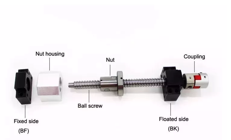
When selecting a ball screw for your application, there are several factors to consider. This article will discuss high mechanical efficiency, low friction, multiple repair options, and application requirements. Choosing the right ball screw can help you get the job done quickly and effectively. To make your decision easier, consider the following tips. Read on to learn about some of the advantages of ball screws and how they can benefit your applications. Here are some of the most common types:
air-compressor

High mechanical efficiency

The mechanical efficiency of ball screws can be measured using the axial load test. The axial load is equal to 0.5 x FPr / 2Fpr. The elastic deformations are measured as DL1 and DL2, respectively. Common engineering procedures work at 90 percent reliability; however, certain sectors require higher reliability, which has a direct impact on the dynamic load capacity. The axial load test is 1 of the most widely used methods to determine the mechanical efficiency of ball screws.
In order to achieve high translation, ball screws must be designed with high stiffness and positioning accuracy. In addition, high preloads increase the initial driving torque and cause more friction and heat. Other important design criteria include low driving torque and reduced slip motion. This means that the high translation capacity of ball screws must be well matched to the overall application. The following are some common design criteria for ball screws. You can select the best type of ball screw for your needs.
The high mechanical efficiency of ball screw is achieved by avoiding the common sag and pitch problem. The ball track design helps to reduce the centrifugal force. The ball screw's diameter can be adjusted by adjusting the centre pitch of the nut on 2 ball tracks. The nut's axial load is also adjusted through the offset centre pitch. This method allows the users to increase the mechanical efficiency of ball screw by up to 40%.
When calculating the mechanical efficiency of ball screw, consider the application's environment, speed, and other factors. If the application requires precision and accuracy, then the ball screw is the right choice. The engineering department of a ball screw manufacturer will carefully review the application factors and come up with a design that meets the application's expectations. Moreover, some manufacturers even offer customized ball screws, which can be tailored to your requirements.

Low friction

The operating performance of a low-friction ball screw is characterized by its minimal friction. This screw has a structure that transmits forces through rolling steel balls. The torque is calculated by calculating the load and the lead screw's dimensions. This type of screw can be used for a variety of different applications, including hydraulic systems. Read on to learn more about this type of screw and how it can help you build a more reliable and durable car.
The critical speed of a ball screw is higher than that of a lead screw, so this type of screw can accommodate larger loads and speeds. It also has a lower friction coefficient, which reduces the amount of heat produced. High-quality ball screws can withstand longer duty cycles than standard lead screws. However, in order to compare the two, you must take into account the duty cycle. Low-friction ball screws are more durable than lead screws, and the duty cycle is only 1 of the factors you should consider when selecting them.
The ball bearings are the most prominent component of a low-friction ball screw. Their main function is to reduce the friction between the nut and the shaft. Without them, the friction would be too high. This feature is possible thanks to the ball bearing's groove profile. Two arcs intersect at the contact points on the shaft and nut. Consequently, the ball bearing reduces friction in a way that is essentially non-existent without the bearing.
The mechanical efficiency of a low-friction ball screw is very high. The typical ball screw is up to 90% efficient, but some types can reach a higher efficiency. They are commonly used in machine slides, presses, and linear actuators. The high efficiency of a low-friction ball screw makes it a great choice for many different applications. This type of screw is made of several main components. The ball bearings provide the helical raceway for the ball assembly and threaded shaft is the screw part. The ball screw is comparatively more bulky than a conventional leadscrew, but the overall size is smaller than its lead counterpart.
air-compressor

Multiple repair options

A damaged ball screw will typically display visible physical signs, including noise or vibration. Additionally, worn ball screws will require more horsepower and torque to operate. They may also cause lead accuracy issues. Luckily, there are multiple repair options for ball screws. You can get new ball screws to restore preload and reduce backlash. But there are some warning signs to look out for first. Keeping a close eye on your ball screw's health can help you avoid a costly replacement.
Look for a ball screw repair company with a proven track record of servicing all types of ball screws. The service should offer a free evaluation and 3 types of service: reload, recondition, and replacement. Reload is the simplest option and involves cleaning and polishing the screw and ball nut. Reconditioning or replacement, on the other hand, requires new parts. Choose the 1 that offers the best value for your money.
EP offers an emergency service and superior service for your ball screws. Their UK service includes delivery and international shipping. All ballscrew repairs are covered by a full service warranty, and the company is known for providing competitive pricing. If you do need a ball screw repair, look no further. Contact K+S today to discuss your specific needs. You'll be glad you did. You'll save up to 70% over purchasing a new ball screw.
While ball screw repair is an easy and inexpensive option, it may be necessary to have it replaced more frequently than the usual. In addition to replacing worn ball screws, you may need to consider a different type of repair. This process involves grinding the ball nut and journal diameters back to their original size. Fortunately, level 4 is the most expensive but can restore a screw's lifespan. This is also the most extensive type of repair available for a ball screw.

Application requirements

A ball screw is an efficient solution for precision motion control in many applications, including automotive and aerospace. These screw-type devices are highly resistant to corrosion, and the alternating steel-ceramic architecture ensures extreme reliability and sturdiness. For the aerospace sector, a ball screw replaces the typical hydraulic system, and the product is used in wind turbine blade pitch and directional position, solar panel movement, and gate control in hydroelectric stations. Ball screws are also used in motorised inspection tables, step photolithography machines, microscopic integrated circuits, and many other applications.
The most critical requirements for a ball screw assembly are backlash and bearing support. Backlash is the amount of axial motion between the screw and nut, which leads to positioning errors. Although this axial motion is minimal, it can be as little as 70um. If the preload is too large, a ball screw may suffer from excessive heat. Depending on the application, the amount of preload required can be adjusted to maximize the overall performance of the device.
The choice of screw is determined by the load capacity. For example, plastic nuts are commonly used for light loads, while bronze nuts are used for loads that weigh several thousand pounds. Lead screws are not particularly reliable in situations where load requirements are extremely high, and a ball screw will often be a better option. The lower friction of a ball screw allows it to withstand higher duty cycles than a lead screw. When the load requirements exceed lead screws' capacity, a ball screw is the better choice.
A step photolithography machine is another example of an application where ball screws play an important role. This device helps manufacturers produce microscopic integrated circuits by harnessing the reaction of light. A stepper is a critical piece of this machine, as it controls the positioning of light exposure on the silicon wafer. High precision is required for this application. Ultimately, a ball screw will make the process easier. Its proven record for meeting instrumentation requirements is an excellent example of its value in the laboratory.
air-compressor

Cost

The global market for ball screws is growing at a steady pace, but what drives the growth? In the ball screw industry, performance, cost, and analytical predictability are the primary concerns of OEMs. This market study provides in-depth analysis of these market dynamics. You'll learn how to best compete in the global market for ball screws. Here are some tips to help you get started:
Ensure you have a good grasp of the differences between lead and ball screws. The cost of lead screws depends on their efficiency, and some of them can achieve C5 level accuracy. However, ball screws are more durable and more repeatable. Besides, lead screws can't achieve high precision because of their sliding motion, which gradually grinds away the accuracy. As a result, the cost of a ball screw is more than compensated by the improved performance of OEMs.
To get the best price for ball screw, look for a manufacturer with a strong technical force. Most of these manufacturers have sophisticated equipment and strict quality control systems. They draw inspiration from the requirements of the market and have continuously increased their technological content to stay ahead of the competition. If you're in Pune, look for a manufacturer with this technology. It won't be difficult to do business with such a supplier. The company will also provide you with contact information, including their office address and phone numbers.
When choosing between lead and ball screws, you need to understand how they work and why they're more reliable. Ball screws are more durable than lead screws, which is 1 of the primary reasons for their popularity. Lead screws, on the other hand, are often used for vertical applications. Lead screws tend to be cheaper than ball screws, but they have more limitations. When used properly, however, they can increase the life and performance of machines. In general, they're corrosion-resistant and offer great design flexibility.

China factory Factory Supplied Customized Aluminum/Carbon Steel Connecting Shaft with CNC Machining     with Good qualityChina factory Factory Supplied Customized Aluminum/Carbon Steel Connecting Shaft with CNC Machining     with Good quality

China Professional Brush Cutter Nylon Grass Trimmer Head For Grass Cutting with Great quality

Product Description

Product Description

Brush Cutter Nylon Grass Trimmer Head For Grass Cutting

Power Type Petrol / Gas
Cutting Type Cutting Grass
Displacement All Displacement Brushcutters
Application Fields Agriculture And Forestry


Packaging & Shipping

Company Profile


Customer Feedback


We Can do READY TO SHIP
1.24 HOURS SHIPPMENT
2.MIN. ORDER:1 PIECE
3.MORE THAN 10000 PARTS IN STOCK


FAQ

1.WHAT IS YOUR WARRANTY TERM?

Our company offer 1% free spare parts to FCL order.There is a 12months warranty for our export products

 from the date of the shipment.If warranty has run out,our customer should pay for the replacement parts. 

 2.IS THE SAMPLE AVAILABLE?

YES,Usually we send the samples by TNT,DHL,FEDEX or UPS,it will take around 3 days for our customers

 to receive them,but customer will charge all cost related to the samples,such as sample cost and airmail

 freight.We will refund our customer the sample cost after receiving its order

 3.WHAT IS YOUR MOQ?

The minimum order amount should be at last USD5,000.00

 4.CAN I USE MY OWN LOGO AND DESIGN ON PRODUCTS?

YES,OEM is welcomed

5.HOW LONG IS THE DELIVERY TIME?

A:2-7 days for the sample order

B:20-30 days for LCL or FCL order

About PARADISE

HangZhou CZPT Garden Tools Co., Ltd. is a global manufacturer in the outdoor power equipment parts industry Since 2013, Our Product Line covers most of the well- known O E M's in the market. The replacement spare parts fits for chainsaw, brush cutter, earth auger, Sprayer, lawn mover, water pump, generator, High pressure washer, Compressor, Welding machine, Construction machine and other garden tools.
Paradise garden warehouse have more than 30000 pcs different parts in stock, can ship fast. The products are exported to more than 60 countries and regions including South Korea, Vietnam, India, Thailand, Russia, the United Kingdom, Canada, the United States, Brazil, Mexico, Ukraine. Besides offering great prices and product to the wholesale customer, we are also continuing to focus on the Small Business Owner. We continue to ship most orders within 1 business day and offer significant savings.
All CZPT products benefit from the latest technology in their design and manufacture, providing excellent ergonomics, outstanding performance, efficiency. engineered for durability and best cost performance. We continue to offer the same superior customer service that we did over 12 years ago and treat each order with the same utmost care and respect as we did with the very first order.
With production inspect system and development teams, CZPT are become 1 of the leader for garden tools spare parts supplier in China.

How to Design a Forging Spur Gear

Before you start designing your own spur gear, you need to understand its main components. Among them are Forging, Keyway, Spline, Set screw and other types. Understanding the differences between these types of spur gears is essential for making an informed decision. To learn more, keep reading. Also, don't hesitate to contact me for assistance! Listed below are some helpful tips and tricks to design a spur gear. Hopefully, they will help you design the spur gear of your dreams.
Gear

Forging spur gears

Forging spur gears is 1 of the most important processes of automotive transmission components. The manufacturing process is complex and involves several steps, such as blank spheroidizing, hot forging, annealing, phosphating, and saponification. The material used for spur gears is typically 20CrMnTi. The process is completed by applying a continuous through extrusion forming method with dies designed for the sizing band length L and Splitting angle thickness T.
The process of forging spur gears can also use polyacetal (POM), a strong plastic commonly used for the manufacture of gears. This material is easy to mold and shape, and after hardening, it is extremely stiff and abrasion resistant. A number of metals and alloys are used for spur gears, including forged steel, stainless steel, and aluminum. Listed below are the different types of materials used in gear manufacturing and their advantages and disadvantages.
A spur gear's tooth size is measured in modules, or m. Each number represents the number of teeth in the gear. As the number of teeth increases, so does its size. In general, the higher the number of teeth, the larger the module is. A high module gear has a large pressure angle. It's also important to remember that spur gears must have the same module as the gears they are used to drive.

Set screw spur gears

A modern industry cannot function without set screw spur gears. These gears are highly efficient and are widely used in a variety of applications. Their design involves the calculation of speed and torque, which are both critical factors. The MEP model, for instance, considers the changing rigidity of a tooth pair along its path. The results are used to determine the type of spur gear required. Listed below are some tips for choosing a spur gear:
Type A. This type of gear does not have a hub. The gear itself is flat with a small hole in the middle. Set screw gears are most commonly used for lightweight applications without loads. The metal thickness can range from 0.25 mm to 3 mm. Set screw gears are also used for large machines that need to be strong and durable. This article provides an introduction to the different types of spur gears and how they differ from 1 another.
Pin Hub. Pin hub spur gears use a set screw to secure the pin. These gears are often connected to a shaft by dowel, spring, or roll pins. The pin is drilled to the precise diameter to fit inside the gear, so that it does not come loose. Pin hub spur gears have high tolerances, as the hole is not large enough to completely grip the shaft. This type of gear is generally the most expensive of the three.
Gear

Keyway spur gears

In today's modern industry, spur gear transmissions are widely used to transfer power. These types of transmissions provide excellent efficiency but can be susceptible to power losses. These losses must be estimated during the design process. A key component of this analysis is the calculation of the contact area (2b) of the gear pair. However, this value is not necessarily applicable to every spur gear. Here are some examples of how to calculate this area. (See Figure 2)
Spur gears are characterized by having teeth parallel to the shafts and axis, and a pitch line velocity of up to 25 m/s is considered high. In addition, they are more efficient than helical gears of the same size. Unlike helical gears, spur gears are generally considered positive gears. They are often used for applications in which noise control is not an issue. The symmetry of the spur gear makes them especially suitable for applications where a constant speed is required.
Besides using a helical spur gear for the transmission, the gear can also have a standard tooth shape. Unlike helical gears, spur gears with an involute tooth form have thick roots, which prevents wear from the teeth. These gears are easily made with conventional production tools. The involute shape is an ideal choice for small-scale production and is 1 of the most popular types of spur gears.

Spline spur gears

When considering the types of spur gears that are used, it's important to note the differences between the two. A spur gear, also called an involute gear, generates torque and regulates speed. It's most common in car engines, but is also used in everyday appliances. However, 1 of the most significant drawbacks of spur gears is their noise. Because spur gears mesh only 1 tooth at a time, they create a high amount of stress and noise, making them unsuitable for everyday use.
The contact stress distribution chart represents the flank area of each gear tooth and the distance in both the axial and profile direction. A high contact area is located toward the center of the gear, which is caused by the micro-geometry of the gear. A positive l value indicates that there is no misalignment of the spline teeth on the interface with the helix hand. The opposite is true for negative l values.
Using an upper bound technique, Abdul and Dean studied the forging of spur gear forms. They assumed that the tooth profile would be a straight line. They also examined the non-dimensional forging pressure of a spline. Spline spur gears are commonly used in motors, gearboxes, and drills. The strength of spur gears and splines is primarily dependent on their radii and tooth diameter.
SUS303 and SUS304 stainless steel spur gears

Stainless steel spur gears are manufactured using different techniques, which depend on the material and the application. The most common process used in manufacturing them is cutting. Other processes involve rolling, casting, and forging. In addition, plastic spur gears are produced by injection molding, depending on the quantity of production required. SUS303 and SUS304 stainless steel spur gears can be made using a variety of materials, including structural carbon steel S45C, gray cast iron FC200, nonferrous metal C3604, engineering plastic MC901, and stainless steel.
The differences between 304 and 303 stainless steel spur gears lie in their composition. The 2 types of stainless steel share a common design, but have varying chemical compositions. China and Japan use the letters SUS304 and SUS303, which refer to their varying degrees of composition. As with most types of stainless steel, the 2 different grades are made to be used in industrial applications, such as planetary gears and spur gears.
Gear

Stainless steel spur gears

There are several things to look for in a stainless steel spur gear, including the diametral pitch, the number of teeth per unit diameter, and the angular velocity of the teeth. All of these aspects are critical to the performance of a spur gear, and the proper dimensional measurements are essential to the design and functionality of a spur gear. Those in the industry should be familiar with the terms used to describe spur gear parts, both to ensure clarity in production and in purchase orders.
A spur gear is a type of precision cylindrical gear with parallel teeth arranged in a rim. It is used in various applications, such as outboard motors, winches, construction equipment, lawn and garden equipment, turbine drives, pumps, centrifuges, and a variety of other machines. A spur gear is typically made from stainless steel and has a high level of durability. It is the most commonly used type of gear.
Stainless steel spur gears can come in many different shapes and sizes. Stainless steel spur gears are generally made of SUS304 or SUS303 stainless steel, which are used for their higher machinability. These gears are then heat-treated with nitriding or tooth surface induction. Unlike conventional gears, which need tooth grinding after heat-treating, stainless steel spur gears have a low wear rate and high machinability.

China Professional Brush Cutter Nylon Grass Trimmer Head For Grass Cutting     with Great qualityChina Professional Brush Cutter Nylon Grass Trimmer Head For Grass Cutting     with Great quality

China Hot selling Aftermarket Diesel Engine Parts K19 Crankshaft for CZPT Application Crank Shaft All Model 4bt 4h 6bt 6CT/6D114 6L Nt855 Nh220 M11 K19 A2300 Isf2.8L Isf3.8L with Free Design Custom

Product Description

Products Name: 
Aftermarket Diesel Engine Parts K19 Crankshaft for CZPT Application

Products Description:

Item Spec.
Engine Maker Cummins
Material Casting 
N.W. (kg) 169
Length (mm) 1324.8
Main journal (mm) 139.7
Rod Journal (mm) 101.6
Stroke (mm) 79.37

Except K19, We can also provide other CZPT Crankshaft as following:

Name Model Material

CUMMINS 4BT Casting
4H Casting
6BT Casting
4HE1 forged
6HK1 forged
6D15T forged
6D34T forged
6CT/6D114 Casting/forged
B3.3(M16/18) Casting
6L Casting
NT855/D85 Casting
NH220/D80 Casting
M11 Casting
K19 Casting
A2300 Casting
ISF2.8L Casting
ISF3.8L Casting

If you can't find out what you wanted, our engineering team are willing to develop specific model per your drawing or sample. 

Our Crankshaft can covered most famous engine brands such as:
 CATERPILLAR :   
S4K S6K 320D 3306 3304 C13 C9 3066

MITSUBISHI :   
S4Q 4D30/4D31 4D32 4D33/4D34 4D34T 4D35 4D55 4D56/T 4D56T-2 4D56U 4DR5 4G15 4G54 4G63 4G64 4M40 S4S S6S S6KT 4D130 S4E S4F 6D14/15 6D16 6D16T 6D17 6D31 6D34 6D22 6D24 8DC91 6D40 6G72 6DB1 4G93 4G94 4M40 6D16

ISUZU :  
4HF1/4HG1T 4HK1/4HE1T 4BA1 4BC2(DB33) 4BG1 4FC1 4JA1 4JB1 4DA1 4JB1T 4BE1 4JG1 4JG2 C223 C240 C190 600P 4BB1A 4ZE1 4ZD1 4ZA1 4ZB1 4BD1 4JJ1 G161 6BB1(NEW) 6BB1(OLB) 6BG1 6HE1 6HK1 6SD1 6WA1 6WG1 6HH1 6QA1 6BD1T/DB58/6BF1 6BD1 6SA1 DH100 10PC1 10PB1 10PE1 10PD1 12PC1 12PD1 6RB1

KOMATSU :   
4D94E/4TNE94 4D95E/4D95S 4D95L 4D102 4D130 3D95 6D95L 6D102 S6D105 6D110 6D108 6D125 6D155

HINO :   
W04D/EM505 W06D W06E J05E J08C/J08E H07C/H07CT H07D EK100 EK100-II EM100 EH700 NE6 P11C P11C new EF750 EF750-2

CUMMINS : 
4BT 4H 6BT 6CT/6D114 6L NT855 NH220 M11 K19 A2300 ISF2.8L ISF3.8L

DEUTZ  :  
F6L912 F6L913 2F1011 F4L912 F4L913 BF4L913 F2L912 F3L912 F3L1011 226B

PERKINS :   
4.236/4.248 4.203/D4.203 3.152/D3.152

NISSAN :   
A12 ED33 FD6 KA20 KR30 ND6 SD23 TD27 YD25 TD42 PE6(T) PD6 FE6T H20-2 k25/K24 KA24 RD8 K21 YD25T RF8 RE8 RF10

Hyundai :   
D4EA D4CB D4BB D4BH D4DA D4DB D4AE G4KC/G4JS D4BA D4AF D6BR D6BJ D6BH D6AV D6AZ D6AB D8AV D8AY D8AB D4AE G4KC G4JS

MERCEDES-BENZ :  
OM442 OM355A(6601) OM355/6(6801) OM360 OM314 OM352 OM366

YANMAR :   
4TNV94/98 4TNE94/98 3TNV84 4TNV84/88 4TNE84/88 4D106 4D122

MAZADA :   
SL VA NA R2 WL 2.0 3.0

STEYR :  
WD615 WD618 WD408.40

TOYOTA :  
13B 14B 1DZ 1RZ/2RZ 2LT 2L 2Z 2TR B/1B 1C/2C 1Z 3B 3L 3L(A) 3RZ 21R/22R 3Y/4Y   3L/5L 12R 2E 2J 1AZ 2AZ 2KD 4K 4P 5M 5R 3B 1Y 2Y 3SZ 4K/5K 4Y 3Y   1NZ 1KZ 11Z 1HZ/1HD-T 1FZ-1 1FZ 14Z 11Z/13Z

MAN :   
D2156 D2366/EC12/DE12 DO846/D1146/DE08 DB58 D2876 D2566 D2066 D2866

Volvo :    
TD100A/101 TD121

Iveco :   
3.0L 2.3L 2.8L

Kubota :   
V3300 V2403 V2203 V3800

Others :   
GM6.5-V8 GM LV-21  GM  T16 JCD3CX FIAT480 Peugeot
504  505 KAMAZ DEAWOO  DC23 
LAND ROVER DISCOVERY LAND ROVET

Why It is Ruich Value:
Ruich Value (HangZhou) Tech. Co., Ltd is a professional auto parts integrated company which located in China old industry base HangZhou. 

Our company are dedicated in engine components production and distribution for 2 decades years, Following are our advantage: 

1) Over 30 years' experiences in engine part manufacturing and after-sales services; 

2) 20 plus seasoned internal technical support engineers; 

3) More than 10 years' experiences in exporting Crankshafts/Camshaft/Turbo etc...And business covers in North America, Latin America, Asia, Africa and Europe etc....; 

4) Three types of certifications: ISO 9001, Chinese Industry and Commerce Bureau certified reliable supplier; And China's AAA-Level credit enterprise; 

5) Partners with many leading renowned companies, such as: CZPT (Fortune Global 500 Corporation), and many engine companies; 

6) Dedicated to offering various crankshaft, camshaft, turbo and we are keeping enriching our product lines. 

7) Provides custom products and private labeling services per clients' demands. 

8) Suitable for famous brands, such as: Toyota, Mitsubishi, Nissan, Isuzu, Volkswagen, Mazda, Hino, Komatsu, Yanmar, Cummins, Caterpillar, Deutz, Hyundai etc… More than 150 kinds of crankshaft, camshaft, turbo etc… And covers from small cars to heavy steam and construction machinery's engine. 

Products Package:

Delivery:

Contact:


Analytical Approaches to Estimating Contact Pressures in Spline Couplings

A spline coupling is a type of mechanical connection between 2 rotating shafts. It consists of 2 parts - a coupler and a coupling. Both parts have teeth which engage and transfer loads. However, spline couplings are typically over-dimensioned, which makes them susceptible to fatigue and static behavior. Wear phenomena can also cause the coupling to fail. For this reason, proper spline coupling design is essential for achieving optimum performance.
splineshaft

Modeling a spline coupling

Spline couplings are becoming increasingly popular in the aerospace industry, but they operate in a slightly misaligned state, causing both vibrations and damage to the contact surfaces. To solve this problem, this article offers analytical approaches for estimating the contact pressures in a spline coupling. Specifically, this article compares analytical approaches with pure numerical approaches to demonstrate the benefits of an analytical approach.
To model a spline coupling, first you create the knowledge base for the spline coupling. The knowledge base includes a large number of possible specification values, which are related to each other. If you modify 1 specification, it may lead to a warning for violating another. To make the design valid, you must create a spline coupling model that meets the specified specification values.
After you have modeled the geometry, you must enter the contact pressures of the 2 spline couplings. Then, you need to determine the position of the pitch circle of the spline. In Figure 2, the centre of the male coupling is superposed to that of the female spline. Then, you need to make sure that the alignment meshing distance of the 2 splines is the same.
Once you have the data you need to create a spline coupling model, you can begin by entering the specifications for the interface design. Once you have this data, you need to choose whether to optimize the internal spline or the external spline. You'll also need to specify the tooth friction coefficient, which is used to determine the stresses in the spline coupling model 20. You should also enter the pilot clearance, which is the clearance between the tip 186 of a tooth 32 on 1 spline and the feature on the mating spline.
After you have entered the desired specifications for the external spline, you can enter the parameters for the internal spline. For example, you can enter the outer diameter limit 154 of the major snap 54 and the minor snap 56 of the internal spline. The values of these parameters are displayed in color-coded boxes on the Spline Inputs and Configuration GUI screen 80. Once the parameters are entered, you'll be presented with a geometric representation of the spline coupling model 20.

Creating a spline coupling model 20

The spline coupling model 20 is created by a product model software program 10. The software validates the spline coupling model against a knowledge base of configuration-dependent specification constraints and relationships. This report is then input to the ANSYS stress analyzer program. It lists the spline coupling model 20's geometric configurations and specification values for each feature. The spline coupling model 20 is automatically recreated every time the configuration or performance specifications of the spline coupling model 20 are modified.
The spline coupling model 20 can be configured using the product model software program 10. A user specifies the axial length of the spline stack, which may be zero, or a fixed length. The user also enters a radial mating face 148, if any, and selects a pilot clearance specification value of 14.5 degrees or 30 degrees.
A user can then use the mouse 110 to modify the spline coupling model 20. The spline coupling knowledge base contains a large number of possible specification values and the spline coupling design rule. If the user tries to change a spline coupling model, the model will show a warning about a violation of another specification. In some cases, the modification may invalidate the design.
In the spline coupling model 20, the user enters additional performance requirement specifications. The user chooses the locations where maximum torque is transferred for the internal and external splines 38 and 40. The maximum torque transfer location is determined by the attachment configuration of the hardware to the shafts. Once this is selected, the user can click "Next" to save the model. A preview of the spline coupling model 20 is displayed.
The model 20 is a representation of a spline coupling. The spline specifications are entered in the order and arrangement as specified on the spline coupling model 20 GUI screen. Once the spline coupling specifications are entered, the product model software program 10 will incorporate them into the spline coupling model 20. This is the last step in spline coupling model creation.
splineshaft

Analysing a spline coupling model 20

An analysis of a spline coupling model consists of inputting its configuration and performance specifications. These specifications may be generated from another computer program. The product model software program 10 then uses its internal knowledge base of configuration dependent specification relationships and constraints to create a valid three-dimensional parametric model 20. This model contains information describing the number and types of spline teeth 32, snaps 34, and shoulder 36.
When you are analysing a spline coupling, the software program 10 will include default values for various specifications. The spline coupling model 20 comprises an internal spline 38 and an external spline 40. Each of the splines includes its own set of parameters, such as its depth, width, length, and radii. The external spline 40 will also contain its own set of parameters, such as its orientation.
Upon selecting these parameters, the software program will perform various analyses on the spline coupling model 20. The software program 10 calculates the nominal and maximal tooth bearing stresses and fatigue life of a spline coupling. It will also determine the difference in torsional windup between an internal and an external spline. The output file from the analysis will be a report file containing model configuration and specification data. The output file may also be used by other computer programs for further analysis.
Once these parameters are set, the user enters the design criteria for the spline coupling model 20. In this step, the user specifies the locations of maximum torque transfer for both the external and internal spline 38. The maximum torque transfer location depends on the configuration of the hardware attached to the shafts. The user may enter up to 4 different performance requirement specifications for each spline.
The results of the analysis show that there are 2 phases of spline coupling. The first phase shows a large increase in stress and vibration. The second phase shows a decline in both stress and vibration levels. The third stage shows a constant meshing force between 300N and 320N. This behavior continues for a longer period of time, until the final stage engages with the surface.
splineshaft

Misalignment of a spline coupling

A study aimed to investigate the position of the resultant contact force in a spline coupling engaging teeth under a steady torque and rotating misalignment. The study used numerical methods based on Finite Element Method (FEM) models. It produced numerical results for nominal conditions and parallel offset misalignment. The study considered 2 levels of misalignment - 0.02 mm and 0.08 mm - with different loading levels.
The results showed that the misalignment between the splines and rotors causes a change in the meshing force of the spline-rotor coupling system. Its dynamics is governed by the meshing force of splines. The meshing force of a misaligned spline coupling is related to the rotor-spline coupling system parameters, the transmitting torque, and the dynamic vibration displacement.
Despite the lack of precise measurements, the misalignment of splines is a common problem. This problem is compounded by the fact that splines usually feature backlash. This backlash is the result of the misaligned spline. The authors analyzed several splines, varying pitch diameters, and length/diameter ratios.
A spline coupling is a two-dimensional mechanical system, which has positive backlash. The spline coupling is comprised of a hub and shaft, and has tip-to-root clearances that are larger than the backlash. A form-clearance is sufficient to prevent tip-to-root fillet contact. The torque on the splines is transmitted via friction.
When a spline coupling is misaligned, a torque-biased thrust force is generated. In such a situation, the force can exceed the torque, causing the component to lose its alignment. The two-way transmission of torque and thrust is modeled analytically in the present study. The analytical approach provides solutions that can be integrated into the design process. So, the next time you are faced with a misaligned spline coupling problem, make sure to use an analytical approach!
In this study, the spline coupling is analyzed under nominal conditions without a parallel offset misalignment. The stiffness values obtained are the percentage difference between the nominal pitch diameter and load application diameter. Moreover, the maximum percentage difference in the measured pitch diameter is 1.60% under a torque of 5000 N*m. The other parameter, the pitch angle, is taken into consideration in the calculation.

China Hot selling Aftermarket Diesel Engine Parts K19 Crankshaft for CZPT Application Crank Shaft All Model 4bt 4h 6bt 6CT/6D114 6L Nt855 Nh220 M11 K19 A2300 Isf2.8L Isf3.8L     with Free Design CustomChina Hot selling Aftermarket Diesel Engine Parts K19 Crankshaft for CZPT Application Crank Shaft All Model 4bt 4h 6bt 6CT/6D114 6L Nt855 Nh220 M11 K19 A2300 Isf2.8L Isf3.8L     with Free Design Custom

China Standard Trailer ATV Kart Golf Scooter Lawnmower Quad Spare Motorcycle Tyre near me factory

Product Description

                                           We'd love to hear from you.

Product information
 

ITEM NO SIZE P.R. PCS / 20'GP MAX P.S.I LOAD STHangZhouRD RIM
COMPRESSED NATURAL  INFLATED KG / LBS
A-033 22"*7.00"-12" 6       28 290 / 638 12"*5.0"
22"*10.00"-12" 6       28 335 / 737 12"*8.0"
23"*8.00"-11" 6       28 290 / 638 11"*6.5"
24"*8.00"-11" 6       28 290 / 638 11"*6.5"
24"*8.00"-12" 6       28 290 / 638 12"*6.5"
24"*9.00"-11" 6       28 290 / 638 11"*7.0"
24"*11.00"-10" 6 544 369 291 28 335 / 737 10"*9.0"
24"*10.00"-11" 6 582 393  311 28 335 / 737 11"*8.5"
25"*8.00"-12" 6 705 447  370 28 290 / 638 12"*6.5"
25"*10.00"-12" 6 560 357  300 28 335 / 737 12"*8.0"
25"*11.00"-10" 6       28 206 / 455 10"*9.0"
25"*11.00"-12" 6 560 357  300 28 335 / 737 12"*9.0"
26"*8.00"-12" 6 490 352  300 28 300 / 660 12"*6.0"
26"*9.00"-12" 6 490 352  300 28 290 / 638 12"*7.0"
26"*10.00"-12" 6 436 322  275 28 300 / 660 12"*8.0"
26"*11.00"-12" 6 408 285  245 28 335 / 737 12"*9.0"
26"*9.00"-14" 6 490 352  300 28 290 / 638 14"*7.0"
26"*11.00"-14" 6 408 285  245 28 335 / 737 14"*9.0"
27"*9.00"-12" 6 420 324  277 28 290 / 638 12"*7.0"
27"*12.00"-12" 6 378 260  228 28 335 / 737 12"*9.0"
27"*9.00"-14" 6 420 324  277 28 290 / 638 14"*7.0"
27"*11.00"-14" 6 378 260  228 28 335 / 737 14"*9.0"
28"*9.00"-12"   (premium rubber compound) 6 /     28 290 / 638 12"*7.0"
28"*9.00"-12"   (premium rubber compound) 8 /     28 335 / 737 12"*7.0"
28"*11.00"-12"   (premium rubber compound) 6 /     28 335 / 737 12"*9.0"
28"*11.00"-12"   (premium rubber compound) 8 /     28 380 / 836 12"*9.0"
29"*9.00"-14"   (premium rubber compound) 6 /     28 290 / 638 14"*7.0"
29"*9.00"-14"   (premium rubber compound) 8 /     28 335 / 737 14"*7.0"
29"*11.00"-14" (premium rubber compound) 6 /     28 335 / 737 14"*9.0"
29"*11.00"-14" (premium rubber compound) 8 /     28 380 / 836 14"*9.0"
30"*10.00"R14" (premium rubber compound) 6 /     28 363/800 14"*8.0"
30"*10.00"R14" (premium rubber compound) 8 /     28 454/1000 14"*8.0"

Test Equipment:

Service:

1.High quality products with competitive price.(Almost 15 years production experience,and you can buy directly from factory.)
2.Excellent before and after market service.(Reply within 24 Hrs,patient and  clear response.)
3.1 Sample available with freight collect.

Atv with A-033 pattern tire.

For more infomation,please kindly feel free to contact with us.
 

Spiral Gears for Right-Angle Right-Hand Drives

Spiral gears are used in mechanical systems to transmit torque. The bevel gear is a particular type of spiral gear. It is made up of 2 gears that mesh with 1 another. Both gears are connected by a bearing. The 2 gears must be in mesh alignment so that the negative thrust will push them together. If axial play occurs in the bearing, the mesh will have no backlash. Moreover, the design of the spiral gear is based on geometrical tooth forms.
Gear

Equations for spiral gear

The theory of divergence requires that the pitch cone radii of the pinion and gear be skewed in different directions. This is done by increasing the slope of the convex surface of the gear's tooth and decreasing the slope of the concave surface of the pinion's tooth. The pinion is a ring-shaped wheel with a central bore and a plurality of transverse axes that are offset from the axis of the spiral teeth.
Spiral bevel gears have a helical tooth flank. The spiral is consistent with the cutter curve. The spiral angle b is equal to the pitch cone's genatrix element. The mean spiral angle bm is the angle between the genatrix element and the tooth flank. The equations in Table 2 are specific for the Spread Blade and Single Side gears from Gleason.
The tooth flank equation of a logarithmic spiral bevel gear is derived using the formation mechanism of the tooth flanks. The tangential contact force and the normal pressure angle of the logarithmic spiral bevel gear were found to be about 20 degrees and 35 degrees respectively. These 2 types of motion equations were used to solve the problems that arise in determining the transmission stationary. While the theory of logarithmic spiral bevel gear meshing is still in its infancy, it does provide a good starting point for understanding how it works.
This geometry has many different solutions. However, the main 2 are defined by the root angle of the gear and pinion and the diameter of the spiral gear. The latter is a difficult 1 to constrain. A 3D sketch of a bevel gear tooth is used as a reference. The radii of the tooth space profile are defined by end point constraints placed on the bottom corners of the tooth space. Then, the radii of the gear tooth are determined by the angle.
The cone distance Am of a spiral gear is also known as the tooth geometry. The cone distance should correlate with the various sections of the cutter path. The cone distance range Am must be able to correlate with the pressure angle of the flanks. The base radii of a bevel gear need not be defined, but this geometry should be considered if the bevel gear does not have a hypoid offset. When developing the tooth geometry of a spiral bevel gear, the first step is to convert the terminology to pinion instead of gear.
The normal system is more convenient for manufacturing helical gears. In addition, the helical gears must be the same helix angle. The opposite hand helical gears must mesh with each other. Likewise, the profile-shifted screw gears need more complex meshing. This gear pair can be manufactured in a similar way to a spur gear. Further, the calculations for the meshing of helical gears are presented in Table 7-1.
Gear

Design of spiral bevel gears

A proposed design of spiral bevel gears utilizes a function-to-form mapping method to determine the tooth surface geometry. This solid model is then tested with a surface deviation method to determine whether it is accurate. Compared to other right-angle gear types, spiral bevel gears are more efficient and compact. CZPT Gear Company gears comply with AGMA standards. A higher quality spiral bevel gear set achieves 99% efficiency.
A geometric meshing pair based on geometric elements is proposed and analyzed for spiral bevel gears. This approach can provide high contact strength and is insensitive to shaft angle misalignment. Geometric elements of spiral bevel gears are modeled and discussed. Contact patterns are investigated, as well as the effect of misalignment on the load capacity. In addition, a prototype of the design is fabricated and rolling tests are conducted to verify its accuracy.
The 3 basic elements of a spiral bevel gear are the pinion-gear pair, the input and output shafts, and the auxiliary flank. The input and output shafts are in torsion, the pinion-gear pair is in torsional rigidity, and the system elasticity is small. These factors make spiral bevel gears ideal for meshing impact. To improve meshing impact, a mathematical model is developed using the tool parameters and initial machine settings.
In recent years, several advances in manufacturing technology have been made to produce high-performance spiral bevel gears. Researchers such as Ding et al. optimized the machine settings and cutter blade profiles to eliminate tooth edge contact, and the result was an accurate and large spiral bevel gear. In fact, this process is still used today for the manufacturing of spiral bevel gears. If you are interested in this technology, you should read on!
The design of spiral bevel gears is complex and intricate, requiring the skills of expert machinists. Spiral bevel gears are the state of the art for transferring power from 1 system to another. Although spiral bevel gears were once difficult to manufacture, they are now common and widely used in many applications. In fact, spiral bevel gears are the gold standard for right-angle power transfer.While conventional bevel gear machinery can be used to manufacture spiral bevel gears, it is very complex to produce double bevel gears. The double spiral bevel gearset is not machinable with traditional bevel gear machinery. Consequently, novel manufacturing methods have been developed. An additive manufacturing method was used to create a prototype for a double spiral bevel gearset, and the manufacture of a multi-axis CNC machine center will follow.
Spiral bevel gears are critical components of helicopters and aerospace power plants. Their durability, endurance, and meshing performance are crucial for safety. Many researchers have turned to spiral bevel gears to address these issues. One challenge is to reduce noise, improve the transmission efficiency, and increase their endurance. For this reason, spiral bevel gears can be smaller in diameter than straight bevel gears. If you are interested in spiral bevel gears, check out this article.
Gear

Limitations to geometrically obtained tooth forms

The geometrically obtained tooth forms of a spiral gear can be calculated from a nonlinear programming problem. The tooth approach Z is the linear displacement error along the contact normal. It can be calculated using the formula given in Eq. (23) with a few additional parameters. However, the result is not accurate for small loads because the signal-to-noise ratio of the strain signal is small.
Geometrically obtained tooth forms can lead to line and point contact tooth forms. However, they have their limits when the tooth bodies invade the geometrically obtained tooth form. This is called interference of tooth profiles. While this limit can be overcome by several other methods, the geometrically obtained tooth forms are limited by the mesh and strength of the teeth. They can only be used when the meshing of the gear is adequate and the relative motion is sufficient.
During the tooth profile measurement, the relative position between the gear and the LTS will constantly change. The sensor mounting surface should be parallel to the rotational axis. The actual orientation of the sensor may differ from this ideal. This may be due to geometrical tolerances of the gear shaft support and the platform. However, this effect is minimal and is not a serious problem. So, it is possible to obtain the geometrically obtained tooth forms of spiral gear without undergoing expensive experimental procedures.
The measurement process of geometrically obtained tooth forms of a spiral gear is based on an ideal involute profile generated from the optical measurements of 1 end of the gear. This profile is assumed to be almost perfect based on the general orientation of the LTS and the rotation axis. There are small deviations in the pitch and yaw angles. Lower and upper bounds are determined as - 10 and -10 degrees respectively.
The tooth forms of a spiral gear are derived from replacement spur toothing. However, the tooth shape of a spiral gear is still subject to various limitations. In addition to the tooth shape, the pitch diameter also affects the angular backlash. The values of these 2 parameters vary for each gear in a mesh. They are related by the transmission ratio. Once this is understood, it is possible to create a gear with a corresponding tooth shape.
As the length and transverse base pitch of a spiral gear are the same, the helix angle of each profile is equal. This is crucial for engagement. An imperfect base pitch results in an uneven load sharing between the gear teeth, which leads to higher than nominal loads in some teeth. This leads to amplitude modulated vibrations and noise. In addition, the boundary point of the root fillet and involute could be reduced or eliminate contact before the tip diameter.

China Standard Trailer ATV Kart Golf Scooter Lawnmower Quad Spare Motorcycle Tyre     near me factory China Standard Trailer ATV Kart Golf Scooter Lawnmower Quad Spare Motorcycle Tyre     near me factory

China OEM All Kinds of Tractor Implements for CZPT near me shop

Product Description

Product Description:

40hp 4wd China agriculture manufacturer price mini garden farm farming tractors for sale
 

This model 40hp 4wd tractor sells very well for its good quality and cheap price.
We export this model tractors most to Europe, America, Australia and Brizil and other countries, they are very popular in the market.

With beautiful appearance, this tractor is also multi-functional. It can match all kinds of farming implements.

Pictures:

Standard Equipments: 

4L23 Engine,4 Cylinders,8+2 Gear Shift,With Single-Stage Clutch,Power Steering,Trailer outlet,
protection plate,Tires:6.0-16/9.5-24,hand throttle wire ,
4x4 Wheel Drive,Front Ballast,Rear Ballast,
3-Point Linkage, Rear PTO 540/760, Color follow your need.

Options:
Cab,Canopy,Multi-Way Valve,Air Brake,Dual-Stage Clutch, 8+8 Shuttle Gear,11.2-24 Tires,
Tilting Draw Bar, Combination Instrument,Iron crate packing,

40hp 4wd Tractor Specs 
 

                     Model CP404
Dimensions of Tractor(mm) Length (to front ballast) 3300
Width 1560
Height (to the exhaust vent) 1896
Tread Front Wheel 1200
Rear Wheel 1200
Axle Base 1690
Min.Ground Clearance 300
Structure weight (kg) 1300
  Engine Model LD4L23
Type Vertical,4-Cylinder,Water Cooled and 4-stroke
Rated Power(kw) 29.4
Rated speed (r/min) 2400
Fuel Diesel
     Tires Front Wheel 6.00-16/6.5-16
Rear Wheel 9.5-24/11.2-24
Clutch Single-stage clutch
    Steering Hydraulic steering
    Transmission Type 8+2  shift
Suspension Type 3-point links
 PTO Type and Rev Semi-independent Type 720r/m or 540/760r/m
Spline Size I35 Rectangle Spline with 6 teeth

TZ-4 Front End Loader with 4 - in - 1 Bucket Specifications:

Model TZ-4
Bucket capacity(m3) 0.3
Rated Load(Kg) 360
Overall dimensions(mm) 4100×1600×1580
Max. dump height(mm) 2000
Max. dump distance(mm) 900
Bucket rollback angle (degree) 420
Max. unloading angle  (degree) 470
Max. scraping depth(mm) 140
Lifting time to pivot pin(s) 7
Descending time(s) 3.5
Recommended Tractor(hp) 35-50

LW-7 Backhoe Specifications:

Model LW-7
Bucket Capacity(m3) 0.036
Bucket Wide(mm) 400
Max.digging depth(mm) 2150
Max.digging Radius(mm) 3360
Max.digging Height(mm) 3400
Discharging Height(mm) 1760
Max.digging depth(2ft) Flat bottom(mm) 2000
Swing Angle(degree) 140°
Bucket Rotation(degree) 160°
Dipper stick CZPT Force(Kg) 950
Operating pressure(Mpa) 16

Packaging & Delivery:

-4 units inside 1x40'fcl assembled,
-Delivery time: 30 days after receiving your deposit

Company Information:

Our service:

Certifications:

FAQ:


Axle Spindle Types and Features

The axle spindle is an integral part of your vehicle's suspension. There are several different types and features, including mounting methods, bearings, and functions. Read on for some basic information on axle spindles. The next part of the article will cover how to choose the correct axle spindle for your vehicle. This article will also discuss the different types of spindles available, including the differences between the rear and front bearings.
Driveshaft

Features

The improved axle spindle nut assembly is capable of providing additional performance benefits, including increased tire life and reduced seal failure. Its keyway features and radially inwardly extending teeth allow nut adjustment to be accomplished with precision. The invention further provides a unique, multi-piece locking mechanism that minimizes leakage and torque transfer. Its principles and features are detailed in the appended claims. For example, the improved axle spindle nut assembly is designed for use in vehicles that are equipped with a steering system.
The axle spindle nut assembly includes a nut 252 with threads 256 on its inner periphery. The axle spindle 50 also features threads 198 on its outer periphery. The nut is threaded onto the outboard end of the axle spindle 50 until it contacts the inboard surface of the axle spacer 26. In the assembled state, a bearing spacer 58 is also present on the axle spindle.
The axle spindle nut assembly can reduce axial end play between the wheel end assembly 52 and the axle spindle 50. It can be tightened to an extreme torque level, but if the thread faces separate, it will undercompress the bearing cone and spacer group. To minimize these disadvantages, the axle spindle nut assembly is a critical component of a wheel-end assembly. There are several types of axle spindle nuts.
The third embodiment of the axle spindle nut assembly 300 comprises an inner washer 202, an outer washer 310, and at least 1 screw 320. The axle spindle nut assembly 300 secures and preloads bearing cones 55, 57. Unlike the first embodiment, the axle spindle nut assembly 300 uses the inner washer 202, which is optional in the third embodiment. The inner washer 202 and outer washer 310 are similar to those of the first embodiment.

Functions

An axle spindle is 1 of the most important components of a vehicle's suspension system. The spindle retains the position of bearings and a spacer in an axle by providing clamp force. The inner nut of an axle spindle should be properly torqued to ensure a secure fit. A spindle nut is also responsible for compressing bearings and spacers. If any of these components are missing, the spindle will not work properly.
An axle spindle is used in rear wheel drive cars. It carries the weight of the vehicle on the axle casing and transfers the torque from the differential to the wheels. The axle spindle and hub are secured on the spindle by large nuts. The axle spindle is a vital component of rear wheel drive vehicles. Hence, it is essential to understand the functions of axle spindle. These components are responsible for the smooth operation of a vehicle's suspension system.
Axle spindles can be mounted in 3 ways: in the typical axle assembly, the spindles are bolted onto the ends of the tubular axle, and the axle is suspended by springs. Short stub-axle mounting uses a torsion beam that flexes to provide a smooth ride. A second washer is used to prevent excessive rotation of the axle spindle.
Apart from being a crucial component of the suspension system, the spindles of the wheels are responsible for guiding the vehicle in a straight line. They are connected to the steering axis and are used in different types of suspension systems. European cars use a MacPherson Strut suspension system in which the spindle is connected to the arms in the front and rear of the suspension frame. The MacPherson strut allows the shock absorber housing to turn the wheel.
Driveshaft

Methods of mounting

Various methods of mounting axle spindle are available. In general, these methods involve forming a tubular blank of uniform cross section and thickness, and receiving the bearing assembly against it. The spindle is then secured using a collar, which also serves as a bearing stop. In some cases, additional features are used to provide greater security. Some of these features may not be suitable for all applications. But they are generally suitable.
Axle spindle forming is usually done by progressive steps using hollow punches. The metallic body of the punch has an inner work surface, which receives the axle blank. A mandrel is fixed within the work opening of the punch. The punch body's work surface forges the spindle about the mandrel. The punch has 2 ends, a closed and an open one.
A wheeled vehicle axle assembly (10) includes a cylindrical housing member (12 a) and a plurality of spindle mounting flanges (30) secured on the housing member. The spindles (16) are firmly attached to the housing member by means of coupling members. The coupling members are configured to distribute the bending loads imposed on the spindle by the axle. It is important to note that the coupling members can be either threaded or screwed.
Traditionally, axle spindles were made from tubular blanks of irregular thickness. This method allowed for a gradual reduction in diameter and eliminated the need for extra metal within the spindle. Similarly, axles made by cold forming eliminate the need for additional metal in the spindle. In this way, the overall cost of manufacture is also reduced. The material used for manufacturing axles also determines the size and shape of the final product.
Driveshaft

Bearings

A nut 16 is used to retain the wheel bearings on axle spindle 12. The nut comprises several parts. The first portion includes a plurality of threads and a deformable second portion. The nut may be disposed on the inboard or outboard end of the axle spindle. This type of nut is typically secured to the axle spindle by a retaining nut.
The bearings are installed in the spindle to allow the wheel hub to rotate. While bearings are greased, they can dry out over time. Consequently, you may hear a loud clicking sound when turning your vehicle. Alternatively, you may notice grease on the edges of your tires. Bearing failure can cause severe damage to your axle spindle. If you notice any of these symptoms, you may need to replace the bearings on your axle spindle. Fortunately, you can purchase the necessary bearing parts at O'Reilly Auto Parts.
There are 3 ways to mount an axle spindle. A typical axle assembly has the spindles bolted to the ends of the tubular axle. A torsion beam is also used to mount the spindles on the axle. This torsion beam acts like a spring to help make the ride smooth and bump-free. Lastly, the axle spindle is sometimes mounted as a bolt-on component.

Cost

If your axle spindle has been damaged, you may need to have it replaced. This part of the axle is relatively easy to replace, but you need to know how to do it correctly. To replace your axle spindle, you must first remove the damaged one. To do this, a technician will cut the weld. They will then thread the new 1 into the axle tube and torque it to specification. After that, they will weld the new axle spindle into place.
When you are thinking about the cost of an axle spindle replacement, you must first determine if it is worth it for your vehicle. It is generally a good idea to replace the spindle only if it is causing damage to your vehicle. You can also replace your axle housing if it is deteriorating. If you do not replace the spindle, you can risk damaging the axle housing. To save money, you can consider using a repair kit.
You can also purchase an axle nut socket set. Most wrenches have an adjusting socket for this purpose. The socket set should be suitable for most vehicle types. Axle spindle replacement costs around $500 to $600 before tax. However, you should be aware that these costs vary widely based on the type of vehicle you have. The parts can cost between $430 and $480, and the labor can cost anywhere from $50 to 70.

China OEM All Kinds of Tractor Implements for CZPT     near me shop China OEM All Kinds of Tractor Implements for CZPT     near me shop