China Standard CZPT Engine Spare Parts Piston with Piston Rings for All Model with Hot selling

Product Description

Questions and Answer

Customer:What's the payment of this deal?
Answer:
1. For samples, can be :
Western Union, T/T (personal).
2. For orders offically, can be: 
30% T/T at sight, 70 % T/T before shipping

Customer:How can we get our goods?
Answer:
1. For samples, can be:
Fedex, DHL, UPS, EMS
2. For orders offically, can be:
by air, by sea, by train

Customer:How long will we get our goods?
Answer:
1. 5-10 days, can be ready for dispatching.
2. 12-20 days, is the maximum for mass production.

Customer: How about the quality of products we received?
Answer:
If our products got quality problem, please take photos and contact with us within 3-month. We will check the costs and find the best mothod to fix it.

Customer: When can I received your reply?
Answer:
( Chinese time, except for national holidays )
Monday - Sunday
8:30 am - 11: ISF3.8 5258754 3923537 6CT210 3923163 L10 3044448 3925878 6CT 3929161 3923367 K19 3036074 3917707 6CT 4933120 KT 3096680 ISDe 5255257 6CT230 3923537 KT 3096685

ISLE 4987914 6CT240 3923164 3929565 NT 3017349 4941395 6CT260 3925878 NT 3017348 3966721 6CT300 3917707 QSB 4934860 DF D5571477453 ISLE375   NT855 357155 Renaul   6CT EUR02   NT855 357157/3048808/357156 K19 3070703 NH220 6620-31-2571  NT855 215420 QSM11 457101 NT855 3017349 K19 3096681 K38 3076706 NT855 3017348 K19 3096685

How to Compare Different Types of Spur Gears

When comparing different types of spur gears, there are several important considerations to take into account. The main considerations include the following: Common applications, Pitch diameter, and Addendum circle. Here we will look at each of these factors in more detail. This article will help you understand what each type of spur gear can do for you. Whether you're looking to power an electric motor or a construction machine, the right gear for the job will make the job easier and save you money in the long run.
Gear

Common applications

Among its many applications, a spur gear is widely used in airplanes, trains, and bicycles. It is also used in ball mills and crushers. Its high speed-low torque capabilities make it ideal for a variety of applications, including industrial machines. The following are some of the common uses for spur gears. Listed below are some of the most common types. While spur gears are generally quiet, they do have their limitations.
A spur gear transmission can be external or auxiliary. These units are supported by front and rear casings. They transmit drive to the accessory units, which in turn move the machine. The drive speed is typically between 5000 and 6000 rpm or 20,000 rpm for centrifugal breathers. For this reason, spur gears are typically used in large machinery. To learn more about spur gears, watch the following video.
The pitch diameter and diametral pitch of spur gears are important parameters. A diametral pitch, or ratio of teeth to pitch diameter, is important in determining the center distance between 2 spur gears. The center distance between 2 spur gears is calculated by adding the radius of each pitch circle. The addendum, or tooth profile, is the height by which a tooth projects above the pitch circle. Besides pitch, the center distance between 2 spur gears is measured in terms of the distance between their centers.
Another important feature of a spur gear is its low speed capability. It can produce great power even at low speeds. However, if noise control is not a priority, a helical gear is preferable. Helical gears, on the other hand, have teeth arranged in the opposite direction of the axis, making them quieter. However, when considering the noise level, a helical gear will work better in low-speed situations.

Construction

The construction of spur gear begins with the cutting of the gear blank. The gear blank is made of a pie-shaped billet and can vary in size, shape, and weight. The cutting process requires the use of dies to create the correct gear geometry. The gear blank is then fed slowly into the screw machine until it has the desired shape and size. A steel gear blank, called a spur gear billet, is used in the manufacturing process.
A spur gear consists of 2 parts: a centre bore and a pilot hole. The addendum is the circle that runs along the outermost points of a spur gear's teeth. The root diameter is the diameter at the base of the tooth space. The plane tangent to the pitch surface is called the pressure angle. The total diameter of a spur gear is equal to the addendum plus the dedendum.
The pitch circle is a circle formed by a series of teeth and a diametrical division of each tooth. The pitch circle defines the distance between 2 meshed gears. The center distance is the distance between the gears. The pitch circle diameter is a crucial factor in determining center distances between 2 mating spur gears. The center distance is calculated by adding the radius of each gear's pitch circle. The dedendum is the height of a tooth above the pitch circle.
Other considerations in the design process include the material used for construction, surface treatments, and number of teeth. In some cases, a standard off-the-shelf gear is the most appropriate choice. It will meet your application needs and be a cheaper alternative. The gear will not last for long if it is not lubricated properly. There are a number of different ways to lubricate a spur gear, including hydrodynamic journal bearings and self-contained gears.
Gear

Addendum circle

The pitch diameter and addendum circle are 2 important dimensions of a spur gear. These diameters are the overall diameter of the gear and the pitch circle is the circle centered around the root of the gear's tooth spaces. The addendum factor is a function of the pitch circle and the addendum value, which is the radial distance between the top of the gear tooth and the pitch circle of the mating gear.
The pitch surface is the right-hand side of the pitch circle, while the root circle defines the space between the 2 gear tooth sides. The dedendum is the distance between the top of the gear tooth and the pitch circle, and the pitch diameter and addendum circle are the 2 radial distances between these 2 circles. The difference between the pitch surface and the addendum circle is known as the clearance.
The number of teeth in the spur gear must not be less than 16 when the pressure angle is 20 degrees. However, a gear with 16 teeth can still be used if its strength and contact ratio are within design limits. In addition, undercutting can be prevented by profile shifting and addendum modification. However, it is also possible to reduce the addendum length through the use of a positive correction. However, it is important to note that undercutting can happen in spur gears with a negative addendum circle.
Another important aspect of a spur gear is its meshing. Because of this, a standard spur gear will have a meshing reference circle called a Pitch Circle. The center distance, on the other hand, is the distance between the center shafts of the 2 gears. It is important to understand the basic terminology involved with the gear system before beginning a calculation. Despite this, it is essential to remember that it is possible to make a spur gear mesh using the same reference circle.

Pitch diameter

To determine the pitch diameter of a spur gear, the type of drive, the type of driver, and the type of driven machine should be specified. The proposed diametral pitch value is also defined. The smaller the pitch diameter, the less contact stress on the pinion and the longer the service life. Spur gears are made using simpler processes than other types of gears. The pitch diameter of a spur gear is important because it determines its pressure angle, the working depth, and the whole depth.
The ratio of the pitch diameter and the number of teeth is called the DIAMETRAL PITCH. The teeth are measured in the axial plane. The FILLET RADIUS is the curve that forms at the base of the gear tooth. The FULL DEPTH TEETH are the ones with the working depth equal to 2.000 divided by the normal diametral pitch. The hub diameter is the outside diameter of the hub. The hub projection is the distance the hub extends beyond the gear face.
A metric spur gear is typically specified with a Diametral Pitch. This is the number of teeth per inch of the pitch circle diameter. It is generally measured in inverse inches. The normal plane intersects the tooth surface at the point where the pitch is specified. In a helical gear, this line is perpendicular to the pitch cylinder. In addition, the pitch cylinder is normally normal to the helix on the outside.
The pitch diameter of a spur gear is typically specified in millimeters or inches. A keyway is a machined groove on the shaft that fits the key into the shaft's keyway. In the normal plane, the pitch is specified in inches. Involute pitch, or diametral pitch, is the ratio of teeth per inch of diameter. While this may seem complicated, it's an important measurement to understand the pitch of a spur gear.
gear

Material

The main advantage of a spur gear is its ability to reduce the bending stress at the tooth no matter the load. A typical spur gear has a face width of 20 mm and will fail when subjected to 3000 N. This is far more than the yield strength of the material. Here is a look at the material properties of a spur gear. Its strength depends on its material properties. To find out what spur gear material best suits your machine, follow the following steps.
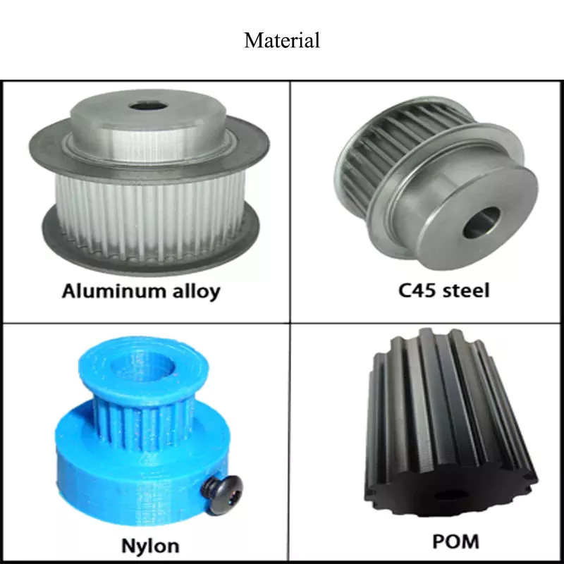
The most common material used for spur gears is steel. There are different kinds of steel, including ductile iron and stainless steel. S45C steel is the most common steel and has a 0.45% carbon content. This type of steel is easily obtainable and is used for the production of helical, spur, and worm gears. Its corrosion resistance makes it a popular material for spur gears. Here are some advantages and disadvantages of steel.
A spur gear is made of metal, plastic, or a combination of these materials. The main advantage of metal spur gears is their strength to weight ratio. It is about 1 third lighter than steel and resists corrosion. While aluminum is more expensive than steel and stainless steel, it is also easier to machine. Its design makes it easy to customize for the application. Its versatility allows it to be used in virtually every application. So, if you have a specific need, you can easily find a spur gear that fits your needs.
The design of a spur gear greatly influences its performance. Therefore, it is vital to choose the right material and measure the exact dimensions. Apart from being important for performance, dimensional measurements are also important for quality and reliability. Hence, it is essential for professionals in the industry to be familiar with the terms used to describe the materials and parts of a gear. In addition to these, it is essential to have a good understanding of the material and the dimensional measurements of a gear to ensure that production and purchase orders are accurate.

China Standard CZPT Engine Spare Parts Piston with Piston Rings for All Model     with Hot sellingChina Standard CZPT Engine Spare Parts Piston with Piston Rings for All Model     with Hot selling

China best Auto Parts Lawn Mower Parts for Mower Filter 698083 697014 697153 Lawn Mower Parts near me supplier

Product Description

auto parts lawn mower parts for mower filter 698083 697014 697153 lawn mower parts

Product Description


Hot Sale Series


ABOUT US
_____________________________LIAN RUN_____________________________


ZheJiang Lianrun Auto Parts Co., Ltd. is Located in Xihu (West Lake) Dis.,ZheJiang .It is a company specializing in the production, development,and sales of filter equipment. The campany has a complete and scientific quality management system and is a key enterprise producting filter in China.
The main products of the company's products include automotive filters,purifier filters, and industrial filters such as air filters. Products cover after market and OEM markets. Products are exported to Europe and the United States, Japan, South Korea,and other countries,good quality and after-sales service has won extensive customer support and praise.

Product Catalogry

FAQ

FAQ

_____________________________LIAN RUN_____________________________

1.-Are you a trading company or manufacturer?

-Manufacturer with factory


2. What kind of product do you produce?

-Covers purifier filters, automotive filters, industrial filters, air filter materials.


3.-How many years did you do filter?

-We have more than 10 years making experience


4.-Is Customized filter available?

-Yes,please offer your required specifications and drawing


5.-Do you Accept OEM service?

-YES!


6.-what's your delivery terms?

-1)FOB 2)CFR 3)CIF


7.-What's your Delivery Time?

-1)generally the samples will be sent immediately by the air express in 3- 5 days if the goods are in stock

-2)Normally within 30 days,please confirm with us before order!


8.-What's the Payment Terms?

-Usually,30% as deposit,70% before shipment by T/T

Western Union acceptable for small amount.

L/C acceptable for large amount. Scrow ,Paybal,Alipay are also ok


9.-How you pack products?

-Normally,plastic bag inside and carton outside .We'll do according to customers' requirement.


10.-What's your available port of Shipment?

-Normally, ZheJiang

Other ports available but you should afford extra charges.


How to Calculate the Diameter of a Worm Gear

worm shaft
In this article, we will discuss the characteristics of the Duplex, Single-throated, and Undercut worm gears and the analysis of worm shaft deflection. Besides that, we will explore how the diameter of a worm gear is calculated. If you have any doubt about the function of a worm gear, you can refer to the table below. Also, keep in mind that a worm gear has several important parameters which determine its working.

Duplex worm gear

A duplex worm gear set is distinguished by its ability to maintain precise angles and high gear ratios. The backlash of the gearing can be readjusted several times. The axial position of the worm shaft can be determined by adjusting screws on the housing cover. This feature allows for low backlash engagement of the worm tooth pitch with the worm gear. This feature is especially beneficial when backlash is a critical factor when selecting gears.
The standard worm gear shaft requires less lubrication than its dual counterpart. Worm gears are difficult to lubricate because they are sliding rather than rotating. They also have fewer moving parts and fewer points of failure. The disadvantage of a worm gear is that you cannot reverse the direction of power due to friction between the worm and the wheel. Because of this, they are best used in machines that operate at low speeds.
Worm wheels have teeth that form a helix. This helix produces axial thrust forces, depending on the hand of the helix and the direction of rotation. To handle these forces, the worms should be mounted securely using dowel pins, step shafts, and dowel pins. To prevent the worm from shifting, the worm wheel axis must be aligned with the center of the worm wheel's face width.
The backlash of the CZPT duplex worm gear is adjustable. By shifting the worm axially, the section of the worm with the desired tooth thickness is in contact with the wheel. As a result, the backlash is adjustable. Worm gears are an excellent choice for rotary tables, high-precision reversing applications, and ultra-low-backlash gearboxes. Axial shift backlash is a major advantage of duplex worm gears, and this feature translates into a simple and fast assembly process.
When choosing a gear set, the size and lubrication process will be crucial. If you're not careful, you might end up with a damaged gear or 1 with improper backlash. Luckily, there are some simple ways to maintain the proper tooth contact and backlash of your worm gears, ensuring long-term reliability and performance. As with any gear set, proper lubrication will ensure your worm gears last for years to come.
worm shaft

Single-throated worm gear

Worm gears mesh by sliding and rolling motions, but sliding contact dominates at high reduction ratios. Worm gears' efficiency is limited by the friction and heat generated during sliding, so lubrication is necessary to maintain optimal efficiency. The worm and gear are usually made of dissimilar metals, such as phosphor-bronze or hardened steel. MC nylon, a synthetic engineering plastic, is often used for the shaft.
Worm gears are highly efficient in transmission of power and are adaptable to various types of machinery and devices. Their low output speed and high torque make them a popular choice for power transmission. A single-throated worm gear is easy to assemble and lock. A double-throated worm gear requires 2 shafts, 1 for each worm gear. Both styles are efficient in high-torque applications.
Worm gears are widely used in power transmission applications because of their low speed and compact design. A numerical model was developed to calculate the quasi-static load sharing between gears and mating surfaces. The influence coefficient method allows fast computing of the deformation of the gear surface and local contact of the mating surfaces. The resultant analysis shows that a single-throated worm gear can reduce the amount of energy required to drive an electric motor.
In addition to the wear caused by friction, a worm wheel can experience additional wear. Because the worm wheel is softer than the worm, most of the wear occurs on the wheel. In fact, the number of teeth on a worm wheel should not match its thread count. A single-throated worm gear shaft can increase the efficiency of a machine by as much as 35%. In addition, it can lower the cost of running.
A worm gear is used when the diametrical pitch of the worm wheel and worm gear are the same. If the diametrical pitch of both gears is the same, the 2 worms will mesh properly. In addition, the worm wheel and worm will be attached to each other with a set screw. This screw is inserted into the hub and then secured with a locknut.

Undercut worm gear

Undercut worm gears have a cylindrical shaft, and their teeth are shaped in an evolution-like pattern. Worms are made of a hardened cemented metal, 16MnCr5. The number of gear teeth is determined by the pressure angle at the zero gearing correction. The teeth are convex in normal and centre-line sections. The diameter of the worm is determined by the worm's tangential profile, d1. Undercut worm gears are used when the number of teeth in the cylinder is large, and when the shaft is rigid enough to resist excessive load.
The center-line distance of the worm gears is the distance from the worm centre to the outer diameter. This distance affects the worm's deflection and its safety. Enter a specific value for the bearing distance. Then, the software proposes a range of suitable solutions based on the number of teeth and the module. The table of solutions contains various options, and the selected variant is transferred to the main calculation.
A pressure-angle-angle-compensated worm can be manufactured using single-pointed lathe tools or end mills. The worm's diameter and depth are influenced by the cutter used. In addition, the diameter of the grinding wheel determines the profile of the worm. If the worm is cut too deep, it will result in undercutting. Despite the undercutting risk, the design of worm gearing is flexible and allows considerable freedom.
The reduction ratio of a worm gear is massive. With only a little effort, the worm gear can significantly reduce speed and torque. In contrast, conventional gear sets need to make multiple reductions to get the same reduction level. Worm gears also have several disadvantages. Worm gears can't reverse the direction of power because the friction between the worm and the wheel makes this impossible. The worm gear can't reverse the direction of power, but the worm moves from 1 direction to another.
The process of undercutting is closely related to the profile of the worm. The worm's profile will vary depending on the worm diameter, lead angle, and grinding wheel diameter. The worm's profile will change if the generating process has removed material from the tooth base. A small undercut reduces tooth strength and reduces contact. For smaller gears, a minimum of 14-1/2degPA gears should be used.
worm shaft

Analysis of worm shaft deflection

To analyze the worm shaft deflection, we first derived its maximum deflection value. The deflection is calculated using the Euler-Bernoulli method and Timoshenko shear deformation. Then, we calculated the moment of inertia and the area of the transverse section using CAD software. In our analysis, we used the results of the test to compare the resulting parameters with the theoretical ones.
We can use the resulting centre-line distance and worm gear tooth profiles to calculate the required worm deflection. Using these values, we can use the worm gear deflection analysis to ensure the correct bearing size and worm gear teeth. Once we have these values, we can transfer them to the main calculation. Then, we can calculate the worm deflection and its safety. Then, we enter the values into the appropriate tables, and the resulting solutions are automatically transferred into the main calculation. However, we have to keep in mind that the deflection value will not be considered safe if it is larger than the worm gear's outer diameter.
We use a four-stage process for investigating worm shaft deflection. We first apply the finite element method to compute the deflection and compare the simulation results with the experimentally tested worm shafts. Finally, we perform parameter studies with 15 worm gear toothings without considering the shaft geometry. This step is the first of 4 stages of the investigation. Once we have calculated the deflection, we can use the simulation results to determine the parameters needed to optimize the design.
Using a calculation system to calculate worm shaft deflection, we can determine the efficiency of worm gears. There are several parameters to optimize gearing efficiency, including material and geometry, and lubricant. In addition, we can reduce the bearing losses, which are caused by bearing failures. We can also identify the supporting method for the worm shafts in the options menu. The theoretical section provides further information.

China best Auto Parts Lawn Mower Parts for Mower Filter 698083 697014 697153 Lawn Mower Parts     near me supplier China best Auto Parts Lawn Mower Parts for Mower Filter 698083 697014 697153 Lawn Mower Parts     near me supplier

China OEM EPA/Carb Certificated Rubber Fuel Hose for All-Terrain Vehicle/ATV /Motorcycle /Lawn Mowers /Garden Machinery wholesaler

Product Description

Products Details
 

Product: EPA/Carb Certificated Rubber Fuel Hose for All-Terrain Vehicle/ATV /Motorcycle /Lawn Mowers /Garden Machinery
Item No.: JBD-A001
Size: ID ≥Φ2.5 mm;
Customized as Required.
Material: FKM;
FKM/ECO;
FKM/ECO/AR/ECO
Structure: 1 to 4-layers
Color: Black
Application Use for All-Terrain Vehicle (ATV), Motorcycle,Outdoor Power Equipments,Garden Machinery,Off-Road Engines,Marine Engines and Generators.
EPA & CARB CERTIFICATE YES.
Standard SAE, YDK,HES, EX-S,ASTM and so on
   
Shipping Port HangZhou 
OEM/ODM Accepted
Package PE bag+Carton+Pallet
Payment Terms T/T, L/C,Western Union
Factory ISO/TS16949:2009 registered
Technical Teams 30+ Years experience
Sample Leadtime 7-15 days
Production Leadtime 20-30 days

Structure of Hose

Our Company:

Product Development Proceducre

Test Equipment:

Our Unique Advantages:

A: 30+ Years Experienced Professional Technical Teams with strong R&D Center.
 
B: Powerful Capacity with 4 Production Factories Base.

C: Stable Quality and Competitive Price----We are an integrated company combining Rubber Raw Materials Refining & Mixer Process and manufacturing Rubber products with professional Technics, as well as Rubber Raw Materials Wholesales.

D: Good & In Time Service----all the enquiry will be processed within 24 hours with satisfactory service before and after sale.

E: Delivery time----15-20 days for mass production.

EPA & CARB CERTIFICATE:
We've achieved the CARB & EPA Certificates use in North America.

Process of Quality Control

Products Collections

Packaging & Shipment

FAQ

Q1. Do your products have EPA/CARB Certificates?
 A. Yes, our products achieve EPA& CARB Certificates.
 

Q2.  Do your products meet RoHS?
Yes, all of our products are green products meet RoHS, REACH.

Q3.  Would you accept OEM/ODM ?
A.  Yes, OEM/ODM can be acceptable.  
Most of our products are customized and manufactured as per client's Drawings and Requirements.

Q4. Do you provide PPAP's ?
 A. Yes,  PPAP's is a basic documents under our IATF16949 certificate.

Q5.  What's the payment terms ?
A. T/T and L/C is acceptable .  30% downpayment and balance before shipments by T/T. Or 100% irrevocable LC at sight.  

Q6.  What kinds of materials are available to manufacture?
A. Our main Rubber & Plastic materials are NBR,SBR,NR,ACM,AEM,CSM,ECO,FKM,VMQ, EPDM,SILICONE,PVC,TPU,ect.


Industrial applications of casing

For rotating and sliding parts, bushings are an important part of the machine. Due to their anti-friction properties and load-carrying capacity, they are an important part of many different industrial processes. Bushings play a vital role in industries such as construction, mining, hydropower, agriculture, transportation, food processing and material handling. To learn more about the benefits of bushings, read on. You'll be amazed how much they can help your business!
bushing

type

When comparing enclosure types, consider the material and how it will be used. Oilite bushings are made of porous material that draws lubricant into the liner and releases it when pressure is applied. These are manufactured using a sintered or powered metal process. Copper and tin are the most commonly used materials for making copper bushings, but there are other types of metal bushings as well.
Another popular type is the plain bearing. This type reduces friction between the rotating shaft and the stationary support element. This type provides support and load bearing while relying on soft metal or plastic for lubrication. Journal bearings are used to support the linear motion of the engine crankshaft in large turbines. They are usually babbitt or hydrodynamic with a liquid film lubricant between the 2 halves.
The oil-impregnated paper sleeve is made of high-quality kraft insulating paper. These bushings contain 2 layers of capacitor grading, with the innermost layer electrically connected to the mounting flange. These are mature processes and are widely used in different voltage levels. CZPT Electric (Group) Co., Ltd. provides UHV DC and AC oil-impregnated paper wall bushings for environmental control rooms.
Electrical bushings are used to transmit electricity. These can be transformers, circuit breakers, shunt reactors and power capacitors. The bushing can be built into the bushing or through the bushing. The conductors must be able to carry the rated current without overheating the adjacent insulation. A typical bushing design has a conductor made of copper or aluminum with insulation on all other sides. If the bushing is used in a circuit, the insulation needs to be high enough to prevent any leakage paths.
Voltage and current ratings of electrical bushings. Solid type electrical bushings typically have a center conductor and a porcelain or epoxy insulator. These bushings are used in small distribution transformers and large generator step-up transformers. Their test voltage is typically around 70 kV. Subsequent applications of this bushing may require a lower halfway release limit. However, this is a common type for many other applications.
bushing

application

Various industrial applications involve the use of casing. It is an excellent mechanical and chemical material with a wide range of properties. These compounds are also packaged according to national and international standards. Therefore, bushings are used in many different types of machines and equipment. This article will focus on the main industrial applications of casing. This article will also explain what a casing is and what it can do. For more information, click here. Casing application
Among other uses, bushing assemblies are used in aircraft and machinery. For example, a fuel tank of an aircraft may include baffle isolator 40 . The bushing assembly 16 serves as an interface to the fuel tank, allowing electrical current to flow. It can also be used to isolate 1 component from another. In some cases, bushing assemblies are used to provide a tight fit and reduce electrical resistance, which is important in circuits.
The benefits of casing go beyond reducing energy transmission. They reduce lubrication costs. If 2 metal parts are in direct contact, lubrication is required. Thus, the bushing reduces the need for lubrication. They also allow parts of the car to move freely. For example, rubber bushings may begin to deteriorate due to high internal temperatures or cold weather. Also, oil can affect their performance.
For example, bushing CTs in oil and gas circuit breakers are used as window current transformers. It consists of a toroidal core and secondary windings. The center conductor of the bushing acts as the single-turn primary of the BCT. By tapping the secondary winding, the ratio between primary and secondary can be changed. This information can be found on the asset nameplate.
Among other uses, bushings are used in diagnostic equipment. These components require precise positioning. Fortunately, air sleeves are perfect for this purpose. Their frictionless operation eliminates the possibility of misalignment. In addition, products based on porous media help minimize noise. A casing manufacturer can advise you on the best product for your equipment. Therefore, if you are looking for replacement bushings for your existing equipment, please feel free to contact Daikin.

Material

Dry ferrule cores were selected for study and examined under an Olympus polarizing microscope (BX51-P). Core slices showing layers of aluminum foil with a distance of approximately 2 cm between adjacent capacitor screens. The aluminum foil surface has a multi-layered structure with undulations due to shrinkage and crepe. Differences between the 2 types of foils are also revealed.
A typical metal bushing material consists of a high-strength metal backing and a solid lubricant. These materials have higher load-carrying capacity and low friction during operation. Additionally, they are precision machined to tight tolerances. They also offer better thermal conductivity and better fatigue resistance. The accuracy of the metal bushing is improved due to the re-machining process that takes place after the bearing is assembled. Additionally, metal bushing materials are more resistant to wear than plastic bushing materials.
Plastic bushings are relatively inexpensive and readily available off the shelf. Also, the price of custom plastic bushings is relatively low. However, they are not recommended for heavy duty applications. Plastics degrade under high loads and can damage mating parts. Also, if the plastic bushings are not manufactured accurately, they can become misaligned. These are just some of the reasons for choosing metal bushings over plastic.
A mechanically bonded bushing 40 is placed over the stabilizer bar and compressed into the outer sleeve/bracket assembly. The outer metal member includes slotted holes that compensate for the tolerance stacking between the first and second bushing assemblies. Pre-assembly allows the assembly plant to receive a complete assembly ready for vehicle assembly, rather than sub-assembly at the vehicle manufacturing plant.
bushing

cost

Control arm bushings are a major component of modern vehicle suspension systems. Damaged bushings can negatively affect the handling and performance of your car. Replacing bushings on a car can cost $200 to $500. While that's pretty cheap for a handful of control bushings, replacing the entire suspension system could set you back over $1,200. Thankfully, if you want to repair or replace the bushing yourself, you can do it yourself for a fraction of the cost.
If you decide to replace the control arm bushing yourself, it's best to shop around for the best price. Many auto parts stores offer cheaper bushings that you don't have to spend a fortune on. Even if you don't drive for years, rubber can degrade and create cracks in the material. These cracks can be as deep as three-8hs of an inch. This makes it dangerous to drive a car with damaged control arm bushings.
Hiring a mechanic might be a good idea if you don't like doing the work yourself. You can save money and time by repairing the control arm yourself, but you may have to hire a mechanic to do the job. Replacing the front sway bar bushing alone can cost between $450 and $900. While these components are relatively inexpensive, you can replace them for a better-handling car.
In some cases, sizing the bushings is a more economical option, but if you want to replace your entire suspension system, it's better to buy a brand new lower limit. You can even save labor by buying a replacement part fork with a good lower portion. In addition to improving your car's handling and ride, new bushings will add to your car's overall value. If you are not sure which parts you need, ask your mechanic for a quote.
While the cost of replacing control arm bushings is relatively low, it's a good idea to compare quotes from multiple mechanics. By getting multiple quotes for the same repair, you can save as much as $50 to $100 on the total cost of your car. In addition to labor costs, parts and labor can vary, so shop around to find the mechanic best suited for your car. There's no reason to settle for sub-par service when you can save $50 or more!

China OEM EPA/Carb Certificated Rubber Fuel Hose for All-Terrain Vehicle/ATV /Motorcycle /Lawn Mowers /Garden Machinery     wholesaler China OEM EPA/Carb Certificated Rubber Fuel Hose for All-Terrain Vehicle/ATV /Motorcycle /Lawn Mowers /Garden Machinery     wholesaler

China wholesaler Spindle Assembly Replace 918-04822b 918-04822A 618-04822 for 42" Mower Deck Tractor Riding Mower with All The Mounting Hardware with Free Design Custom

Product Description

Product Description


About this item
TICSEA Spindle Assembly Replace 918- 0571 2B 918- 0571 2A 618- 0571 2 for 42" Mower Deck Tractor Riding Mower, Come with All The Mounting Hardware Including Threaded Bolt

TICSEA Lawn mower spindles help your lawn mower pulley system perform efficiently while giving your lawn mower power.

The spindles and pulleys work together to rotate for a smooth, even cut.

If any parts of the spindle assembly are damaged, it can cause to spin unevenly, or prevent them from spinning at all.

Replacest: 618- 0571 2, 618- 0571 2A, 618-04889, 618-04889A, 618-04950, 918- 0571 2, 918- 0571 2A, 918- 0571 2B, 918-04889, 918-04889A,918-04950.

6.7" Overall Height, 6" Pulley OD, 6 points star blade adaptor. came with the mounting bolts and the spindles were threaded.

This spindle assembly work with 42" mower deck tractor riding mower.
Easy to install, package includes 4 tapped bolts, zerk grease,plastic top nut, convenient and stable.

EASY INSTALLATION: Mounting holes have been pre-tapped for easier installation, Spacer must be installed under the pulley.

Product Parameters


Detailed Photos

Specs
OD of Pulley: 6"
6 pt. star spindle shaft? Pulley included
With threads holes and 4 bolts
Includes: TICSEA Lawn mower spindles
Material:Metal

Package include
* 1 x 187292 Spindle
* 1 x blade bolts
* 1 x pulley nut
* 1 x washer
* 4 x mounting bolts


Fit
618-04636
618-04636A
618-04865
618-04865A
918-04865A
918-04636
918-04636A
918-0865A


Compatile With
LT2000, LT2200, LT2500, YT4622SE, YT946KH, LTX1045, LTX1046, LTX1046VT, LTX1042, LTX1046KW, LTX1046M, Z-Force S 46 inch deck

Similar Product

Company Profile

KL Seating was founded in 2001 with an area of 26000 square meters. We have two manufacturing bases: HangZhou,ZheJiang and HangZhou,ZheJiang . With enough skilled employees,KL Seating has the capacity of producing 400,000pcs seats per year.
We have perfect Management System and excellent R&D team. All of our products has passed ISO9001:2008,CE and PAHS certificate. Our products are mainly for Domestic OEM and overseas aftermarket, like Europe, America, Australia, South Asia,etc.
With the Enterprise Principle of customer first, team work, best service,  KL seating will do the utmost to provide the comfortable and safety seats, striving to be the global seat designer and manufacturer. 


Our Advantages


1. Abundant Products
We have abundant products mainly in spare parts for Agriculture, Lawn & Garden Utility, Industrial and Construction

2. Customer Groups
We welcome all kinds of customer include Wholesalers, distributors, B2B sellers, B2C sellers, individual buyers, OEMs and so on...

3. Quality Control
Patrol inspection during production and full inspection before shipment. What's more, we can have a video call

with you to confirm the goods if you are worried.

4. Fast Delivery
We have Amazon store and Shopify store for individual buyers with fast delivery. If you want to order in Alibaba, we will provide you a discount price which is cheaper than you buy in Amazon or Shopify. The lead time is about 7-30 days for big order. Specific lead time is depended on specific product.


Hypoid Bevel Vs Straight Spiral Bevel - What's the Difference?

Spiral gears come in many different varieties, but there is a fundamental difference between a Hypoid bevel gear and a Straight spiral bevel. This article will describe the differences between the 2 types of gears and discuss their use. Whether the gears are used in industrial applications or at home, it is vital to understand what each type does and why it is important. Ultimately, your final product will depend on these differences.
Gear

Hypoid bevel gears

In automotive use, hypoid bevel gears are used in the differential, which allows the wheels to rotate at different speeds while maintaining the vehicle's handling. This gearbox assembly consists of a ring gear and pinion mounted on a carrier with other bevel gears. These gears are also widely used in heavy equipment, auxiliary units, and the aviation industry. Listed below are some common applications of hypoid bevel gears.
For automotive applications, hypoid gears are commonly used in rear axles, especially on large trucks. Their distinctive shape allows the driveshaft to be located deeper in the vehicle, thus lowering the center of gravity and minimizing interior disruption. This design makes the hypoid gearset 1 of the most efficient types of gearboxes on the market. In addition to their superior efficiency, hypoid gears are very easy to maintain, as their mesh is based on sliding action.
The face-hobbed hypoid gears have a characteristic epicycloidal lead curve along their lengthwise axis. The most common grinding method for hypoid gears is the Semi-Completing process, which uses a cup-shaped grinding wheel to replace the lead curve with a circular arc. However, this method has a significant drawback - it produces non-uniform stock removal. Furthermore, the grinding wheel cannot finish all the surface of the tooth.
The advantages of a hypoid gear over a spiral bevel gear include a higher contact ratio and a higher transmission torque. These gears are primarily used in automobile drive systems, where the ratio of a single pair of hypoid gears is the highest. The hypoid gear can be heat-treated to increase durability and reduce friction, making it an ideal choice for applications where speed and efficiency are critical.
The same technique used in spiral bevel gears can also be used for hypoid bevel gears. This machining technique involves two-cut roughing followed by one-cut finishing. The pitch diameter of hypoid gears is up to 2500 mm. It is possible to combine the roughing and finishing operations using the same cutter, but the two-cut machining process is recommended for hypoid gears.
The advantages of hypoid gearing over spiral bevel gears are primarily based on precision. Using a hypoid gear with only 3 arc minutes of backlash is more efficient than a spiral bevel gear that requires 6 arc minutes of backlash. This makes hypoid gears a more viable choice in the motion control market. However, some people may argue that hypoid gears are not practical for automobile assemblies.
Hypoid gears have a unique shape - a cone that has teeth that are not parallel. Their pitch surface consists of 2 surfaces - a conical surface and a line-contacting surface of revolution. An inscribed cone is a common substitute for the line-contact surface of hypoid bevel gears, and it features point-contacts instead of lines. Developed in the early 1920s, hypoid bevel gears are still used in heavy truck drive trains. As they grow in popularity, they are also seeing increasing use in the industrial power transmission and motion control industries.
Gear

Straight spiral bevel gears

There are many differences between spiral bevel gears and the traditional, non-spiral types. Spiral bevel gears are always crowned and never conjugated, which limits the distribution of contact stress. The helical shape of the bevel gear is also a factor of design, as is its length. The helical shape has a large number of advantages, however. Listed below are a few of them.
Spiral bevel gears are generally available in pitches ranging from 1.5 to 2500 mm. They are highly efficient and are also available in a wide range of tooth and module combinations. Spiral bevel gears are extremely accurate and durable, and have low helix angles. These properties make them excellent for precision applications. However, some gears are not suitable for all applications. Therefore, you should consider the type of bevel gear you need before purchasing.
Compared to helical gears, straight bevel gears are easier to manufacture. The earliest method used to manufacture these gears was the use of a planer with an indexing head. However, with the development of modern manufacturing processes such as the Revacycle and Coniflex systems, manufacturers have been able to produce these gears more efficiently. Some of these gears are used in windup alarm clocks, washing machines, and screwdrivers. However, they are particularly noisy and are not suitable for automobile use.
A straight bevel gear is the most common type of bevel gear, while a spiral bevel gear has concave teeth. This curved design produces a greater amount of torque and axial thrust than a straight bevel gear. Straight teeth can increase the risk of breaking and overheating equipment and are more prone to breakage. Spiral bevel gears are also more durable and last longer than helical gears.
Spiral and hypoid bevel gears are used for applications with high peripheral speeds and require very low friction. They are recommended for applications where noise levels are essential. Hypoid gears are suitable for applications where they can transmit high torque, although the helical-spiral design is less effective for braking. For this reason, spiral bevel gears and hypoids are generally more expensive. If you are planning to buy a new gear, it is important to know which 1 will be suitable for the application.
Spiral bevel gears are more expensive than standard bevel gears, and their design is more complex than that of the spiral bevel gear. However, they have the advantage of being simpler to manufacture and are less likely to produce excessive noise and vibration. They also have less teeth to grind, which means that they are not as noisy as the spiral bevel gears. The main benefit of this design is their simplicity, as they can be produced in pairs, which saves money and time.
In most applications, spiral bevel gears have advantages over their straight counterparts. They provide more evenly distributed tooth loads and carry more load without surface fatigue. The spiral angle of the teeth also affects thrust loading. It is possible to make a straight spiral bevel gear with 2 helical axes, but the difference is the amount of thrust that is applied to each individual tooth. In addition to being stronger, the spiral angle provides the same efficiency as the straight spiral gear.
Gear

Hypoid gears

The primary application of hypoid gearboxes is in the automotive industry. They are typically found on the rear axles of passenger cars. The name is derived from the left-hand spiral angle of the pinion and the right-hand spiral angle of the crown. Hypoid gears also benefit from an offset center of gravity, which reduces the interior space of cars. Hypoid gears are also used in heavy trucks and buses, where they can improve fuel efficiency.
The hypoid and spiral bevel gears can be produced by face-hobbing, a process that produces highly accurate and smooth-surfaced parts. This process enables precise flank surfaces and pre-designed ease-off topographies. These processes also enhance the mechanical resistance of the gears by 15 to 20%. Additionally, they can reduce noise and improve mechanical efficiency. In commercial applications, hypoid gears are ideal for ensuring quiet operation.
Conjugated design enables the production of hypoid gearsets with length or profile crowning. Its characteristic makes the gearset insensitive to inaccuracies in the gear housing and load deflections. In addition, crowning allows the manufacturer to adjust the operating displacements to achieve the desired results. These advantages make hypoid gear sets a desirable option for many industries. So, what are the advantages of hypoid gears in spiral gears?
The design of a hypoid gear is similar to that of a conventional bevel gear. Its pitch surfaces are hyperbolic, rather than conical, and the teeth are helical. This configuration also allows the pinion to be larger than an equivalent bevel pinion. The overall design of the hypoid gear allows for large diameter shafts and a large pinion. It can be considered a cross between a bevel gear and a worm drive.
In passenger vehicles, hypoid gears are almost universal. Their smoother operation, increased pinion strength, and reduced weight make them a desirable choice for many vehicle applications. And, a lower vehicle body also lowers the vehicle's body. These advantages made all major car manufacturers convert to hypoid drive axles. It is worth noting that they are less efficient than their bevel gear counterparts.
The most basic design characteristic of a hypoid gear is that it carries out line contact in the entire area of engagement. In other words, if a pinion and a ring gear rotate with an angular increment, line contact is maintained throughout their entire engagement area. The resulting transmission ratio is equal to the angular increments of the pinion and ring gear. Therefore, hypoid gears are also known as helical gears.

China wholesaler Spindle Assembly Replace 918-04822b 918-04822A 618-04822 for 42China wholesaler Spindle Assembly Replace 918-04822b 918-04822A 618-04822 for 42

China Best Sales All-Terrain Vehicle/ATV Motorcycle Lawn Mowers Garden Machinery Rubber Fuel Line with Hot selling

Product Description

Product: All-Terrain Vehicle/ATV Motorcycle Lawn Mowers Garden Machinery Rubber Fuel Line
Item No.: JBD-E093
Size: ID ≥Φ2.5 mm;
Customized as Required.
Shape: Customized as Required.
Structure 1-4 Layers
Material: FKM/ECO;
FKM/ECO/YARN/ECO;
ACM/YARN/ACM;
NBR/YARN/CSM;
NBR/YARN/NBR+PVC;
NBR+PVC;
NBR+CSM/CM;
NBR; NR;ECO; ECO/CSM;
Structure: 1 to 4-layers
Color: Black
Application Use for Transmission System,Brake System, Clutch Lines,Fuel Supply System,Fuel Tank,Turbo Oil Feed Hose,Oil Pressure System, Gauge lines & Power Steering System in Engine, Motorcycle,Automobile,Trucks, Contruction Machinery,Heavy Equipments, Etc.
EPA & CARB CERTIFICATE YES.
Standard SAE, YDK,HES, EX-S,ASTM and so on
Shipping Port HangZhou 
OEM/ODM Accepted
Package PE bag+Carton+Pallet
Payment Terms T/T, L/C,Western Union
Factory ISO/TS16949:2009 registered
Technical Teams 30+ Years experience
Sample Leadtime 7-15 days
Production Leadtime 30-45 days

Structure of Hose
Our Company:

Product Development Procedure:

Test Equipment:

Our Unique Advantages:

A: 30+ Years Experienced Professional Technical Teams with strong R&D Center.
 
B: Powerful Capacity with 4 Production Factories Base.

C: Stable Quality and Competitive Price----We are an integrated company combining Rubber Raw Materials Refining & Mixer Process and manufacturing Rubber products with professional Technics, as well as Rubber Raw Materials Wholesales.

D: Good & In Time Service----all the enquiry will be processed within 24 hours with satisfactory service before and after sale.

E: Delivery time----15-20 days for mass production.

Certificate:

Process of Quality Control:

Products Collections

Packaging & Shipment

FAQ

Q1. Do your products have EPA/CARB Certificates?
 A. Yes, our products achieve EPA& CARB Certificates.
 

Q2.  Do your products meet RoHS?
Yes, all of our products are green products meet RoHS, REACH.

Q3.  Would you accept OEM/ODM ?
A.  Yes, OEM/ODM can be acceptable.  
Most of our products are customized and manufactured as per client's Drawings and Requirements.

Q4. Do you provide PPAP's ?
 A. Yes,  PPAP's is a basic documents under our IATF16949 certificate.

Q5.  What's the payment terms ?
A. T/T and L/C is acceptable .  30% downpayment and balance before shipments by T/T. Or 100% irrevocable LC at sight.  

Q6.  What kinds of materials are available to manufacture?
A. Our main Rubber & Plastic materials are NBR,SBR,NR,ACM,AEM,CSM,ECO,FKM,VMQ, EPDM,SILICONE,PVC,TPU,ect.


Pulley Type

There are several types of pulleys. These include fixed pulleys, load multipliers and movable pulleys. Below is a description of each pulley type. A load multiplier is a special type of pulley with multiple wheels for increased lifting capacity. It is used in a wide range of applications including power transmission and construction. Some common uses of pulleys are listed below.

moving pulley

Movable pulleys work by transferring the weight of a load to another object of the same mass. Since a live pulley is inherently frictionless and weightless, the force required to lift a load with it is the same as the weight of the load. This principle applies to tall buildings and residences. It is an excellent choice for lifting heavy objects such as furniture and washing machines.
A pulley is a mechanical device with a wheel that rotates on a shaft. The axle is attached to the wheel and is usually fixed. The movable pulley can be fixed or movable, both of which can change the direction of the force on the rope. Some pulleys can also change the magnitude and direction of the force. They are ideal for a variety of applications, from lifting heavy objects to transporting objects.
Another type of movable pulley works by transmitting force to another object. It has a free axis and the total force provided by the rope tension is balanced. Since the tension on the rope is constant in each segment, pulling 1 end of the rope will double the force on the shaft, resulting in 2 mechanical advantages. This mechanical advantage is the main reason why movable pulleys are so versatile.
Another form of moving pulley is called a KWL diagram. The KWL diagram summarizes the basic concepts of the drive wheel. KWL diagrams are an excellent way to assess a student's understanding of the concepts discussed in the course. Word questions are a great way to check whether students understand concepts. When students answer the word questions correctly, the answer is yes!
pulley

Fixed wheel pulley

If you need to move heavy objects, a single fixed wheel pulley is not a good choice. Using a single fixed pulley might be similar to using a handbag, but it's not very convenient. This type of pulley system relies on friction to transmit motion. As a result, it can slip and isn't always reliable. Fortunately, you can find other options that work just as well.
Fixed pulleys are the most basic type of pulley. They consist of grooved wheels and ropes attached to objects. These pulleys make lifting easier. Because the rope or cable only moves in 1 direction, the movement of the object feels lighter. And they are also easy to install. However, before you buy a fixed wheel pulley, make sure it is strong enough to support the weight of the load.
The disadvantages of fixed pulleys are obvious. One of them is the lack of mechanical advantage. A fixed pulley pulls up with the same force as a single moving pulley, and a single fixed pulley is not particularly effective as a force multiplier. However, the effect is more pronounced when you combine multiple fixed-wheel pulleys. You will get double the power! So what do fixed wheel pulleys have to offer?
Fixed wheel pulleys can be as small as a ring. A single ring pulley requires twice as much force as the weight being pulled. Adding more loops to the rope will reduce the effort required to pull the weight. The mechanical advantage of a fixed pulley is proportional to the number of strands running to the free pulley. A 100-pound pull on the free end will lift a 300-pound load.
pulley

composite pulley

Compound pulleys are pulleys that can be used to change the direction of a control wire. It can also be used to modify the mechanical force of the wire by moving the item it is connected to. In galleons, compound pulleys are more common. They are often combined with other ropes for mechanical advantage. Here are some common uses for composite pulleys.
The ideal mechanical advantage of a pulley is equal to the number of rope segments that pull up the load. This means that the more rope segments, the less force is required. A compound pulley will have the ideal mechanical advantage of 2, which means it will generate more force than a simple pulley. Composite pulleys are also more efficient at transmitting force because their number of rope segments is usually equal to the unit weight.
Composite pulley systems use more than 2 pulleys and ropes. More pulleys will reduce the force required to move heavier objects. They are usually used in large sailboats. The system is also used on construction sites. It can be used for a variety of applications, including lifting large objects or transmitting electricity. You can imagine how it would change your life if you had to move a large sailboat, but the result would be the same: a composite pulley system would make it easier to lift a large sailboat.
Composite pulleys are also known as fixed pulleys. The fixed pulley is stationary, and the movable pulley moves back and forth. The latter is more effective when used with a detachable cord or strap. On the other hand, a moving pulley is a moving pulley and it gives you a mechanical advantage. You can imagine this pulley on a flagpole.

load multiplier

The multiplication system has 3 basic parts: the rope grab, the connector, and the pulley. While some basic multipliers may combine the 3 parts, the concept remains the same. The multiplication system can make pulling the rope easier by reducing the amount of friction that occurs. Below are some examples of multiplication systems. A compact rope grab is a great option for resetting the multiplier.
The load reduction that a pulley system can achieve is proportional to the number of ropes used to support it. Although most utility pulley systems use only 4 ropes, the theoretical maximum load reduction is a quarter of the actual load. In other words, the four-wheel system only reduces the weight of a 1,000-pound load by a quarter. That would require 167 pounds of force, a far cry from the 500-pound load a single pulley system can achieve.
The mechanical advantage of a pulley system can be calculated by calculating the ratio between the forces exerted on each wire. For example, a 90-kilogram load is supported by 3 ropes, each weighing about 30-5 pounds. The ropes on pulleys A and B each carry a load of 60 kg. Using this formula, a single pulley system will yield a mechanical advantage over 2 tractors.
To calculate the force required to pull the rope over the pulley, measure the angle and deflection between the ropes. The deflection angle when added to the included angle should equal 180 degrees. A 75 degree angle requires 159% of the load force. This means a total load multiplier of four. This formula is an important tool for calculating the force multiple of the pulley.
pulley

Disadvantages of fixed pulleys

There are 2 basic types of pulleys: movable and fixed. Active pulleys are more advanced, allowing the pulley to move according to the load. They reduce the force required to lift the load. Active roller pulleys are more compact and therefore take up less space. Both types are good for lifting heavier objects, but they each have their pros and cons.
Fixed wheel pulleys can be used to lift heavy objects. This type of pulley consists of a wheel with a fixed shaft that has grooves on its edges for guiding ropes or cables. This is a simple machine as no motor or engine is required to lift objects. When 2 or more wheels are used together, the ropes around the wheels form a powerful hoist.
Single wheel pulleys are not suitable for lifting. They tend to push things down. Also, they are unreliable because they rely on friction and can slip. Also, a single wheel pulley would require a lot of space. Another disadvantage of fixed-wheel pulleys is that they make it difficult to move heavy objects easily. Single fixed-wheel pulleys also tend to slip easily, making them a poor choice for many applications.
Fixed wheel pulleys are also easier to install and maintain than manually operated ones. It requires less space and lubrication than manual pulleys. Manual pulleys can cause injury because the operator will be lifting the full weight of the heavy object. Additionally, rope slippage can lead to muscle strains and rope burns. And the system requires frequent maintenance.

China Best Sales All-Terrain Vehicle/ATV Motorcycle Lawn Mowers Garden Machinery Rubber Fuel Line     with Hot sellingChina Best Sales All-Terrain Vehicle/ATV Motorcycle Lawn Mowers Garden Machinery Rubber Fuel Line     with Hot selling

China OEM Garden Cutting Machine for Trees and Grass All Seasons Lawn Mower with high quality

Product Description

1. What are the main products we are producing?
Kinds of heaters and coolers.
2. What's JEMELL's main advantages?
We can provide customer products with competitive price, better quality, better service.
3. What else that JEMELL can do?
We can design/develop/manufacture customized products.
4. Is logo can be printed?
Yes, silkscreen print, gift box, manuals, labels, carton, all can be customized.
5. What if I need a sample?
Sample can be provided within one week. 
6.What's JEMELL's service?
One year warranty, 1-2% spare parts, OEM&ODM can be provided.

Screw Shaft Types

If you're looking for a screw shaft, but aren't sure which type to buy, you're in luck. In this article, we'll talk about the different types, including Threaded shank, Round head, and Machined. Once you've read it, you'll know which type to buy. Then, you can decide whether you want a ball screw nut or a threaded shank.

Machined screw shafts

Besides the standard stainless steel shaft, manufacturers also provide a variety of other materials, such as titanium, bronze, and brass. In addition to stainless steel, manufacturers also provide a variety of top-coating options, including zinc, brass, and chromium. Aluminum screws are not particularly durable and are easily affected by weather. Most screw shafts feature self-locking mechanisms. They are especially useful in C-clamps, vises, and screw-top container lids.
For applications where accuracy is vital, a ball screw shaft needs to be annealed. A heat treatment can be performed on the ball screw shaft to ensure that both ends are heated evenly. In this process, the shaft will be more durable, while maintaining its high-precision properties. These screw shafts are a key component in computer-controlled motion-control systems, wire bonding, and other industries that require high-precision and high-quality performance.
Depending on the material used, screw shafts can be made of stainless steel or titanium. High-precision CNC machines and lathes are typically used to manufacture screw shafts. Various shapes and sizes are available, each with a specific application. Whether you need a small or large screw, you can find 1 to fit your needs. And since each size requires a different material, your choice of material is important as well.
In general, the materials used for machining screw shafts are steel, stainless steel, titanium, brass, bronze, and aluminum. Metals that resist corrosion are also commonly used. Other materials for screw shafts are Teflon, nylon, and nylon. You can also find threaded screw shafts in materials such as porcelain, glass, and ceramic. If you want to use your screws in a unique material, consider purchasing a customized one.
screwshaft

Ball screw nuts

If you have a screw shaft, the last thing you want to worry about is the ball nut slipping off. To prevent this, you can place a temporary stop in the shaft's grooves to ensure that the ball nut does not slide off. When you remove the stop, you can then install the ball screw nut. But, before you can install the ball screw nut, you have to make sure that you have a good grip on the shaft.
When selecting ball screw nuts, it's important to consider how much preload you need to apply to avoid excessive backlash. Preloading eliminates this problem by making the ball nut compact. It also prevents backlash, which is lost motion caused by clearance between the ball and nut. Backlash disrupts repeatability and accuracy. This is where spacer preloading comes in. You can insert a spacer between the 2 ball nuts to transmit the force to the nut. However, you should keep in mind that this method reduces the load capacity of the ball screw.
The critical speed of a screw is the maximum rotating speed before it whips. This critical speed is influenced by several factors, including the diameter of the screw shaft, the number of support elements, and the material. By adjusting these factors, you can reduce the number of components used and the amount of time it takes to assemble the screw shaft. In addition, you can also reduce the number of components and avoid stacking tolerances. However, the critical speed of plastic nuts is limited due to sliding friction.
The ball screw nut has several characteristics that make it unique. Its most prominent feature is the presence of ball bearings. These balls help reduce friction between the screw nut and the shaft. Without ball bearings, the friction would be too high to function properly. Another important characteristic is the groove profile of the nut and ball. These 2 features ensure that the ball and the nut meet at 2 points. You'll be amazed by the results of the work of these ball screw nuts.
screwshaft

Threaded shank

Wood screws are usually not fully threaded because the shank has an unthreaded portion at the top. This shoulder part forces the screw to compress 2 pieces of wood, which prevents the screw from overheating and compromising the materials strength. As the screw is threaded partially up, it is not as difficult to remove as a fully threaded screw. However, it is important to note that a wood screw will not hold as tightly as 1 with a fully threaded shank.
In addition to being universal, screw threads can be of different sizes. For example, a M8 screw has a thread pitch of 1.25 mm. To avoid confusion, screw thread pitches are commonly given with a multiplication sign. For example, M8x1 means that the screw is 8 mm in diameter but has a thread pitch of 1 mm per 360-degree rotation. Those who are not familiar with these dimensions may find it confusing.
The OD of the threaded portion of a bolt is generally smaller than the OD of the nut. If the shank is too deep for the nut to fit, the threads may bottom out. This is why it's important to use a thread-cutting bit with a small thread diameter. You can use a micrometer or caliper to measure the thread diameter. This tool will also allow you to easily identify which screw size fits where and how well.
The metric system is the most widely used. Fasteners with DIN numbers are generally metric in size. This makes them very useful for industrial settings. You can find metric-sized screws anywhere, as long as you buy them from a reputable manufacturer. These fasteners also come with a dog point, which is used for safety wire. If the screw needs to be replaced, the shank can be drilled with a hole for a safety wire or for a dog-point.

Round head

A round head screw is the most common type used for machine screws. Other common types include truss head, flat head, and hexed head. Each has a different profile and are used for different purposes. A round head screw is typically wider than a flat or a hexed head, and has a slightly rounded surface. These screws are useful for projects involving sheet metal or sheet-metal parts. Round heads are usually slightly wider than a hex head screw, and they may also be used as a substitute for washers in certain applications. However, truss heads are not necessary for every project.
A wood screw has a smooth shank that protrudes above the surface of the material it is attaching. A metal screw has a threaded shaft that is fully threaded from head to point, and a fully threaded shaft provides more bite. Two common head styles are round head and pan head. If the task requires the screw to be flush or countersunk, the round head will be the best choice.
Another type is the Reed & Prince screw drive. These are similar to Phillips screws but have a 75-degree V shape. They are commonly used in marine hardware and are also known as BNAE NFL22-070. This type is also used for steel plate hangers. In addition to round head and pan head screws, there are a variety of other screw types. You can even get a head with a slotted head if you know where to look.
Screw diameters are specified according to the ISO 261 or ISO 262 standards. An M8 screw has a diameter of 8.25 mm. The M8 screw has a pitch of 1.25 mm, which is equivalent to 1 mm per 360 degrees. There are several other standard screw sizes and thread diameters available. You can find them all by consulting the relevant standards. But remember, the metric system is the most popular.
screwshaft

Self-locking mechanism

A self-locking mechanism for a screw shaft is a device that secures the screw to its supporting member in a failure position. The locking mechanism provides a positive connection between the screw shaft and the control surface during normal operation, and locks the screw to its supporting member when the screw fails. Previous attempts to solve this problem have typically used secondary nuts with free play on the screw, which were intentionally designed to jam when loaded. However, such a device can be unreliable, which is why the present invention offers a more robust and reliable locking mechanism.
The self-locking function of a screw depends on several factors, including its pitch angle and the coefficient of friction of the threads. The angle of friction must be less than the tangent of the material pairing to prevent untightening of the screw. Screws with self-locking mechanisms have an efficiency e lower than 50%, which is less than half. Self-locking screws also have the benefit of being less efficient than a standard screw.
Unlike a normal screw, a self-locking screw can be turned in either direction. The nut 22 rotates with the screw shaft, and the member 23 is translated in an axial direction. Regardless of the direction of the rotation of the screw, this axial translation will result in the opposite moment to that input moment. While screw self-locking mechanisms are typically less expensive, they are more reliable and durable.
Another important feature of self-locking screws is that they are not susceptible to independent loosening. The screw cannot rotate without a certain amount of torque. In addition, a self-locking screw shaft must have a small wedge with a smaller half-angle than the arctangent of the static friction. This means that the torque applied by the driver must be greater than the torque needed to overcome the friction.

China OEM Garden Cutting Machine for Trees and Grass All Seasons Lawn Mower     with high qualityChina OEM Garden Cutting Machine for Trees and Grass All Seasons Lawn Mower     with high quality

China Good quality All-Terrain Vehicle/ATV Motorcycle Lawn Mowers Garden Machinery Low Permeation Rubber Fuel Line near me shop

Product Description

Product: All-Terrain Vehicle/ATV Motorcycle Lawn Mowers Garden Machinery Low Permeation Rubber Fuel Line
Item No.: JBD-E095
Size: ID ≥Φ2.5 mm;
Customized as Required.
Shape: Customized as Required.
Structure 1-4 Layers
Material: FKM/ECO;
FKM/ECO/YARN/ECO;
ACM/YARN/ACM;
NBR/YARN/CSM;
NBR/YARN/NBR+PVC;
NBR+PVC;
NBR+CSM/CM;
NBR; NR;ECO; ECO/CSM;
Structure: 1 to 4-layers
Color: Black
Application Use for Transmission System,Brake System, Clutch Lines,Fuel Supply System,Fuel Tank,Turbo Oil Feed Hose,Oil Pressure System, Gauge lines & Power Steering System in Engine, Motorcycle,Automobile,Trucks, Contruction Machinery,Heavy Equipments, Etc.
EPA & CARB CERTIFICATE YES.
Standard SAE, YDK,HES, EX-S,ASTM and so on
Shipping Port HangZhou 
OEM/ODM Accepted
Package PE bag+Carton+Pallet
Payment Terms T/T, L/C,Western Union
Factory ISO/TS16949:2009 registered
Technical Teams 30+ Years experience
Sample Leadtime 7-15 days
Production Leadtime 30-45 days


Structure of Hose

Our Company:

Product Development Procedure:

Test Equipment:

Our Unique Advantages:

A: 30+ Years Experienced Professional Technical Teams with strong R&D Center.
 
B: Powerful Capacity with 4 Production Factories Base.

C: Stable Quality and Competitive Price----We are an integrated company combining Rubber Raw Materials Refining & Mixer Process and manufacturing Rubber products with professional Technics, as well as Rubber Raw Materials Wholesales.

D: Good & In Time Service----all the enquiry will be processed within 24 hours with satisfactory service before and after sale.

E: Delivery time----15-20 days for mass production.

Certificate:

Process of Quality Control:

Products Collections

Packaging & Shipment

FAQ

Q1. Do your products have EPA/CARB Certificates?
 A. Yes, our products achieve EPA& CARB Certificates.
 

Q2.  Do your products meet RoHS?
Yes, all of our products are green products meet RoHS, REACH.

Q3.  Would you accept OEM/ODM ?
A.  Yes, OEM/ODM can be acceptable.  
Most of our products are customized and manufactured as per client's Drawings and Requirements.

Q4. Do you provide PPAP's ?
 A. Yes,  PPAP's is a basic documents under our IATF16949 certificate.

Q5.  What's the payment terms ?
A. T/T and L/C is acceptable .  30% downpayment and balance before shipments by T/T. Or 100% irrevocable LC at sight.  

Q6.  What kinds of materials are available to manufacture?
A. Our main Rubber & Plastic materials are NBR,SBR,NR,ACM,AEM,CSM,ECO,FKM,VMQ, EPDM,SILICONE,PVC,TPU,ect.


Spiral Gears for Right-Angle Right-Hand Drives

Spiral gears are used in mechanical systems to transmit torque. The bevel gear is a particular type of spiral gear. It is made up of 2 gears that mesh with 1 another. Both gears are connected by a bearing. The 2 gears must be in mesh alignment so that the negative thrust will push them together. If axial play occurs in the bearing, the mesh will have no backlash. Moreover, the design of the spiral gear is based on geometrical tooth forms.
Gear

Equations for spiral gear

The theory of divergence requires that the pitch cone radii of the pinion and gear be skewed in different directions. This is done by increasing the slope of the convex surface of the gear's tooth and decreasing the slope of the concave surface of the pinion's tooth. The pinion is a ring-shaped wheel with a central bore and a plurality of transverse axes that are offset from the axis of the spiral teeth.
Spiral bevel gears have a helical tooth flank. The spiral is consistent with the cutter curve. The spiral angle b is equal to the pitch cone's genatrix element. The mean spiral angle bm is the angle between the genatrix element and the tooth flank. The equations in Table 2 are specific for the Spread Blade and Single Side gears from Gleason.
The tooth flank equation of a logarithmic spiral bevel gear is derived using the formation mechanism of the tooth flanks. The tangential contact force and the normal pressure angle of the logarithmic spiral bevel gear were found to be about 20 degrees and 35 degrees respectively. These 2 types of motion equations were used to solve the problems that arise in determining the transmission stationary. While the theory of logarithmic spiral bevel gear meshing is still in its infancy, it does provide a good starting point for understanding how it works.
This geometry has many different solutions. However, the main 2 are defined by the root angle of the gear and pinion and the diameter of the spiral gear. The latter is a difficult 1 to constrain. A 3D sketch of a bevel gear tooth is used as a reference. The radii of the tooth space profile are defined by end point constraints placed on the bottom corners of the tooth space. Then, the radii of the gear tooth are determined by the angle.
The cone distance Am of a spiral gear is also known as the tooth geometry. The cone distance should correlate with the various sections of the cutter path. The cone distance range Am must be able to correlate with the pressure angle of the flanks. The base radii of a bevel gear need not be defined, but this geometry should be considered if the bevel gear does not have a hypoid offset. When developing the tooth geometry of a spiral bevel gear, the first step is to convert the terminology to pinion instead of gear.
The normal system is more convenient for manufacturing helical gears. In addition, the helical gears must be the same helix angle. The opposite hand helical gears must mesh with each other. Likewise, the profile-shifted screw gears need more complex meshing. This gear pair can be manufactured in a similar way to a spur gear. Further, the calculations for the meshing of helical gears are presented in Table 7-1.
Gear

Design of spiral bevel gears

A proposed design of spiral bevel gears utilizes a function-to-form mapping method to determine the tooth surface geometry. This solid model is then tested with a surface deviation method to determine whether it is accurate. Compared to other right-angle gear types, spiral bevel gears are more efficient and compact. CZPT Gear Company gears comply with AGMA standards. A higher quality spiral bevel gear set achieves 99% efficiency.
A geometric meshing pair based on geometric elements is proposed and analyzed for spiral bevel gears. This approach can provide high contact strength and is insensitive to shaft angle misalignment. Geometric elements of spiral bevel gears are modeled and discussed. Contact patterns are investigated, as well as the effect of misalignment on the load capacity. In addition, a prototype of the design is fabricated and rolling tests are conducted to verify its accuracy.
The 3 basic elements of a spiral bevel gear are the pinion-gear pair, the input and output shafts, and the auxiliary flank. The input and output shafts are in torsion, the pinion-gear pair is in torsional rigidity, and the system elasticity is small. These factors make spiral bevel gears ideal for meshing impact. To improve meshing impact, a mathematical model is developed using the tool parameters and initial machine settings.
In recent years, several advances in manufacturing technology have been made to produce high-performance spiral bevel gears. Researchers such as Ding et al. optimized the machine settings and cutter blade profiles to eliminate tooth edge contact, and the result was an accurate and large spiral bevel gear. In fact, this process is still used today for the manufacturing of spiral bevel gears. If you are interested in this technology, you should read on!
The design of spiral bevel gears is complex and intricate, requiring the skills of expert machinists. Spiral bevel gears are the state of the art for transferring power from 1 system to another. Although spiral bevel gears were once difficult to manufacture, they are now common and widely used in many applications. In fact, spiral bevel gears are the gold standard for right-angle power transfer.While conventional bevel gear machinery can be used to manufacture spiral bevel gears, it is very complex to produce double bevel gears. The double spiral bevel gearset is not machinable with traditional bevel gear machinery. Consequently, novel manufacturing methods have been developed. An additive manufacturing method was used to create a prototype for a double spiral bevel gearset, and the manufacture of a multi-axis CNC machine center will follow.
Spiral bevel gears are critical components of helicopters and aerospace power plants. Their durability, endurance, and meshing performance are crucial for safety. Many researchers have turned to spiral bevel gears to address these issues. One challenge is to reduce noise, improve the transmission efficiency, and increase their endurance. For this reason, spiral bevel gears can be smaller in diameter than straight bevel gears. If you are interested in spiral bevel gears, check out this article.
Gear

Limitations to geometrically obtained tooth forms

The geometrically obtained tooth forms of a spiral gear can be calculated from a nonlinear programming problem. The tooth approach Z is the linear displacement error along the contact normal. It can be calculated using the formula given in Eq. (23) with a few additional parameters. However, the result is not accurate for small loads because the signal-to-noise ratio of the strain signal is small.
Geometrically obtained tooth forms can lead to line and point contact tooth forms. However, they have their limits when the tooth bodies invade the geometrically obtained tooth form. This is called interference of tooth profiles. While this limit can be overcome by several other methods, the geometrically obtained tooth forms are limited by the mesh and strength of the teeth. They can only be used when the meshing of the gear is adequate and the relative motion is sufficient.
During the tooth profile measurement, the relative position between the gear and the LTS will constantly change. The sensor mounting surface should be parallel to the rotational axis. The actual orientation of the sensor may differ from this ideal. This may be due to geometrical tolerances of the gear shaft support and the platform. However, this effect is minimal and is not a serious problem. So, it is possible to obtain the geometrically obtained tooth forms of spiral gear without undergoing expensive experimental procedures.
The measurement process of geometrically obtained tooth forms of a spiral gear is based on an ideal involute profile generated from the optical measurements of 1 end of the gear. This profile is assumed to be almost perfect based on the general orientation of the LTS and the rotation axis. There are small deviations in the pitch and yaw angles. Lower and upper bounds are determined as - 10 and -10 degrees respectively.
The tooth forms of a spiral gear are derived from replacement spur toothing. However, the tooth shape of a spiral gear is still subject to various limitations. In addition to the tooth shape, the pitch diameter also affects the angular backlash. The values of these 2 parameters vary for each gear in a mesh. They are related by the transmission ratio. Once this is understood, it is possible to create a gear with a corresponding tooth shape.
As the length and transverse base pitch of a spiral gear are the same, the helix angle of each profile is equal. This is crucial for engagement. An imperfect base pitch results in an uneven load sharing between the gear teeth, which leads to higher than nominal loads in some teeth. This leads to amplitude modulated vibrations and noise. In addition, the boundary point of the root fillet and involute could be reduced or eliminate contact before the tip diameter.

China Good quality All-Terrain Vehicle/ATV Motorcycle Lawn Mowers Garden Machinery Low Permeation Rubber Fuel Line     near me shop China Good quality All-Terrain Vehicle/ATV Motorcycle Lawn Mowers Garden Machinery Low Permeation Rubber Fuel Line     near me shop

China Hot selling Mini Drill Farm Tractor Mounted for All Attachments Grass Cutter Cutting Machine BCS Reaper Mtd Mower Hedge Trimmer Cultivator Shovel Hay Bale Clamp with Best Sales

Product Description

Product Description:

25hp cheap 4x4 mini tractor
 

This model 25hp 4wd tractor sells very well for its good quality and cheap price.
We export this model tractors most to Europe, America, Australia and Brizil and other countries, they are very popular in the market.

With beautiful appearance, this tractor is also multi-functional. It can match all kinds of farming implements.

Pictures:


Standard Equipments: 

LD385 Engine,4 Cylinders,8+2 Gear Shift,With Single-Stage Clutch,Power Steering,Trailer outlet,
protection plate,Tires:6.0-16/9.5-24,hand throttle wire ,
4x4 Wheel Drive,Front Ballast,Rear Ballast,
3-Point Linkage, Rear PTO 540/760, Color follow your need.

Options:
Cab,Canopy,Multi-Way Valve,Air Brake,Dual-Stage Clutch, 8+8 Shuttle Gear,11.2-24 Tires,
Tilting Draw Bar, Combination Instrument,Iron crate packing,

25hp 4wd Tractor Specs 
 

                     Model CP254
Dimensions of Tractor(mm) Length (to front ballast) 3300
Width 1560
Height (to the exhaust vent) 1896
Tread Front Wheel 1200
Rear Wheel 1200
Axle Base 1690
Min.Ground Clearance 300
Structure weight (kg) 1300
  Engine Model LD385
Type Vertical,4-Cylinder,Water Cooled and 4-stroke
Rated Power(kw) 18.4
Rated speed (r/min) 2400
Fuel Diesel
     Tires Front Wheel 6.00-16/6.5-16
Rear Wheel 9.5-24/11.2-24
Clutch Single-stage clutch
    Steering Hydraulic steering
    Transmission Type 8+2  shift
Suspension Type 3-point links
 PTO Type and Rev Semi-independent Type 720r/m or 540/760r/m
Spline Size I35 Rectangle Spline with 6 teeth

Packaging & Delivery:

-4 units inside 1x40'fcl assembled,
-Delivery time: 30 days after receiving your deposit

Company Information:

Our service:

Certifications:

FAQ:


Types of Screw Shafts

Screw shafts come in various types and sizes. These types include fully threaded, Lead, and Acme screws. Let's explore these types in more detail. What type of screw shaft do you need? Which 1 is the best choice for your project? Here are some tips to choose the right screw:

Machined screw shaft

The screw shaft is a basic piece of machinery, but it can be further customized depending on the needs of the customer. Its features include high-precision threads and ridges. Machined screw shafts are generally manufactured using high-precision CNC machines or lathes. The types of screw shafts available vary in shape, size, and material. Different materials are suitable for different applications. This article will provide you with some examples of different types of screw shafts.
Ball screws are used for a variety of applications, including mounting machines, liquid crystal devices, measuring devices, and food and medical equipment. Various shapes are available, including miniature ball screws and nut brackets. They are also available without keyway. These components form a high-accuracy feed mechanism. Machined screw shafts are also available with various types of threaded ends for ease of assembly. The screw shaft is an integral part of linear motion systems.
When you need a machined screw shaft, you need to know the size of the threads. For smaller machine screws, you will need a mating part. For smaller screw sizes, the numbers will be denominated as industry Numeric Sizes. These denominations are not metric, but rather in mm, and they may not have a threads-per-inch designation. Similarly, larger machine screws will usually have threads that have a higher pitch than those with a lower pitch.
Another important feature of machine screws is that they have a thread on the entire shaft, unlike their normal counterparts. These machine screws have finer threads and are intended to be screwed into existing tapped holes using a nut. This means that these screws are generally stronger than other fasteners. They are usually used to hold together electronic components, industrial equipment, and engines. In addition to this, machine screws are usually made of a variety of materials.
screwshaft

Acme screw

An Acme screw is the most common type of threaded shaft available. It is available in a variety of materials including stainless steel and carbon steel. In many applications, it is used for large plates in crushing processes. ACME screws are self-locking and are ideal for applications requiring high clamping force and low friction. They also feature a variety of standard thread forms, including knurling and rolled worms.
Acme screws are available in a wide range of sizes, from 1/8" to 6". The diameter is measured from the outside of the screw to the bottom of the thread. The pitch is equal to the lead in a single start screw. The lead is equal to the pitch plus the number of starts. A screw of either type has a standard pitch and a lead. Acme screws are manufactured to be accurate and durable. They are also widely available in a wide range of materials and can be customized to fit your needs.
Another type of Acme screw is the ball screw. These have no back drive and are widely used in many applications. Aside from being lightweight, they are also able to move at faster speeds. A ball screw is similar to an Acme screw, but has a different shape. A ball screw is usually longer than an Acme screw. The ball screw is used for applications that require high linear speeds. An Acme screw is a common choice for many industries.
There are many factors that affect the speed and resolution of linear motion systems. For example, the nut position and the distance the screw travels can all affect the resolution. The total length of travel, the speed, and the duty cycle are all important. The lead size will affect the maximum linear speed and force output. If the screw is long, the greater the lead size, the higher the resolution. If the lead length is short, this may not be the most efficient option.
screwshaft

Lead screw

A lead screw is a threaded mechanical device. A lead screw consists of a cylindrical shaft, which includes a shallow thread portion and a tightly wound spring wire. This spring wire forms smooth, hard-spaced thread convolutions and provides wear-resistant engagement with the nut member. The wire's leading and trailing ends are anchored to the shaft by means appropriate to the shaft's composition. The screw is preferably made of stainless steel.
When selecting a lead screw, 1 should first determine its critical speed. The critical speed is the maximum rotations per minute based on the natural frequency of the screw. Excessive backlash will damage the lead screw. The maximum number of revolutions per minute depends on the screw's minor diameter, length, assembly alignment, and end fixity. Ideally, the critical speed is 80% of its evaluated critical speed. A critical speed is not exceeded because excessive backlash would damage the lead screw and may be detrimental to the screw's performance.
The PV curve defines the safe operating limits of a lead screw. This relationship describes the inverse relationship between contact surface pressure and sliding velocity. As the PV value increases, a lower rotation speed is required for heavier axial loads. Moreover, PV is affected by material and lubrication conditions. Besides, end fixity, which refers to the way the lead screw is supported, also affects its critical speed. Fixed-fixed and free end fixity are both possible.
Lead screws are widely used in industries and everyday appliances. In fact, they are used in robotics, lifting equipment, and industrial machinery. High-precision lead screws are widely used in the fields of engraving, fluid handling, data storage, and rapid prototyping. Moreover, they are also used in 3D printing and rapid prototyping. Lastly, lead screws are used in a wide range of applications, from measuring to assembly.

Fully threaded screw

A fully threaded screw shaft can be found in many applications. Threading is an important feature of screw systems and components. Screws with threaded shafts are often used to fix pieces of machinery together. Having fully threaded screw shafts ensures that screws can be installed without removing the nut or shaft. There are 2 major types of screw threads: coarse and fine. When it comes to coarse threads, UTS is the most common type, followed by BSP.
In the 1840s, a British engineer named Joseph Whitworth created a design that was widely used for screw threads. This design later became the British Standard Whitworth. This standard was used for screw threads in the United States during the 1840s and 1860s. But as screw threads evolved and international standards were established, this system remained largely unaltered. A new design proposed in 1864 by William Sellers improved upon Whitworth's screw threads and simplified the pitch and surface finish.
Another reason for using fully threaded screws is their ability to reduce heat. When screw shafts are partially threaded, the bone grows up to the screw shaft and causes the cavity to be too narrow to remove it. Consequently, the screw is not capable of backing out. Therefore, fully threaded screws are the preferred choice for inter-fragmentary compression in children's fractures. However, surgeons should know the potential complication when removing metalwork.
The full thread depth of a fully threaded screw is the distance at which a male thread can freely thread into the shaft. This dimension is typically 1 millimeter shy of the total depth of the drilled hole. This provides space for tap lead and chips. The full-thread depth also makes fully threaded screws ideal for axially-loaded connections. It is also suitable for retrofitting applications. For example, fully threaded screws are commonly used to connect 2 elements.
screwshaft

Ball screw

The basic static load rating of a ball screw is determined by the product of the maximum axial static load and the safety factor "s0". This factor is determined by past experience in similar applications and should be selected according to the design requirements of the application. The basic static load rating is a good guideline for selecting a ball screw. There are several advantages to using a ball screw for a particular application. The following are some of the most common factors to consider when selecting a ball screw.
The critical speed limit of a ball screw is dependent on several factors. First of all, the critical speed depends on the mass, length and diameter of the shaft. Second, the deflection of the shaft and the type of end bearings determine the critical speed. Finally, the unsupported length is determined by the distance between the ball nut and end screw, which is also the distance between bearings. Generally, a ball screw with a diameter greater than 1.2 mm has a critical speed limit of 200 rpm.
The first step in manufacturing a high-quality ball screw is the choice of the right steel. While the steel used for manufacturing a ball screw has many advantages, its inherent quality is often compromised by microscopic inclusions. These microscopic inclusions may eventually lead to crack propagation, surface fatigue, and other problems. Fortunately, the technology used in steel production has advanced, making it possible to reduce the inclusion size to a minimum. However, higher-quality steels can be expensive. The best material for a ball screw is vacuum-degassed pure alloy steel.
The lead of a ball screw shaft is also an important factor to consider. The lead is the linear distance between the ball and the screw shaft. The lead can increase the amount of space between the balls and the screws. In turn, the lead increases the speed of a screw. If the lead of a ball screw is increased, it may increase its accuracy. If not, the lead of a ball screw can be improved through preloading, lubrication, and better mounting accuracy.

China Hot selling Mini Drill Farm Tractor Mounted for All Attachments Grass Cutter Cutting Machine BCS Reaper Mtd Mower Hedge Trimmer Cultivator Shovel Hay Bale Clamp     with Best SalesChina Hot selling Mini Drill Farm Tractor Mounted for All Attachments Grass Cutter Cutting Machine BCS Reaper Mtd Mower Hedge Trimmer Cultivator Shovel Hay Bale Clamp     with Best Sales

China high quality Cheaper Price Hydraulic Lawn Mower for All Brands Skid Steer Loader, Excavator and Loader Grass Cutter Brush Slasher for Sale near me shop

Product Description


S402 FS skidsteer attachments Brush Mower Cutter for Sale

Product Description

Brush Cutter use on your skid steer loader is an ideal tool for clearing brush, saplings, smaller trees, scrub and thickets. They are also great for land reclamation, home site clearing, utlity and railroad right-of-way clearing, timber stand improvement, brush mowing, landscaping purposes, underbrush removal and vegetation management. Skid steer brush cutter units are available in various widths to perfectly match your Skid Steer Rotary Brush Cutters needs.
 

Product Parameters


Model S402 60 S402 72 S402 84
Overall Length (mm) 1935 2285 2730
Overall Width (mm) 1720 2030 2230
Overall Height (mm) 590 590 735
Weight(Kg) 440 630 850
Cutting Width(mm) 1530 1830 2140
Cutting Height(mm) 50 50 50
Cutting blade numbers 2 2 2
Flow(l/min) 60-80 75-90 75-90

 
The features:

  1. Three widths are available: 1530mm, 1830mm, 2140mm.
  2.  Grass cutter for skid steer loaders are quality built to width stand the rigours of different conditions.
  3.  Fixed cutting height: 50mm.
  4.  Chain curtain included for debris suppression.
  5.  Fork pockets for easy transportation. Includes hoses and couplings.
  6.  Reinforced slasher deck - 6 mm thick
  7.  High speed hydraulics.
  8.  Motor: Made in China or CZPT Motor.

Detailed Photos


Packaging & Shipping

Company Profile

HangZhou XIHU (WEST LAKE) DIS. MACHINERY TECHNOLOGY CO.,LTD. founded in 2014, we are a professional manufacturer engaged in R & D, production, sales and service of construction machinery attachments. Our main products include: sweeper, pallet fork,vibratory roller, lawn mower, trencher, grapple bucket, tree spade, forest mulcher and so on, which are applicable to JCB, CASE, CAT, VOLVO, CZPT and other well-known brand.

FAQ

Are you factory or trading company?
A) We are ISO9001 certified factory, mainly manufacture in Construction Machinery & Attachments.
B) Using "Self-produced Self-marketing" business, reducing the cost of intermediate links.
What's your company advantages?
A) As the leading manufacturer of construction machines, we have own proffessional design team, we can OEM products according to customer needs.
B) With us your money and your business is safe. We can offer 7-days refund in case of bad quality,
C) Coming together is a beginning; keeping together is progress; working together is success.
Can we buy 1 sample?
Yes, we need to add sample fee to the price and will return it back to your after receiving your large order in future.
What's your delivery time?
After receiving your payment, we start to produce your order. It usually takes about 15-45 days depending on the products you order.
How do you control your quality?
To guarantee high quality and efficient management, we have passed ISO9001 quality management system certificate. All of our products are 100% inspected before shipment. Our whole manufacturing processes are under a very serious and strict system in our company.


Proper Maintenance of Tractor Parts

Proper maintenance of tractor parts is a necessity if you want to keep them running smoothly. Here are some things to keep in mind:

agriculturalparts

Proper maintenance of tractor parts

To ensure that your tractor is operating at peak efficiency, you should perform preventative maintenance on its various parts. Before opening the cab of your tractor, perform a visual inspection to check for any problems. Look for leaking fluids, hoses, and cables. Tighten loose connections, and clean any debris from these components. Also check the sediment bowl under the fuel filter for any material or water. If the sediment bowl has a large amount of material, it may be time to replace the fuel filter or the air filter.

Despite the monetary cost of maintaining your tractor, a few simple things can keep your investment in top condition. For instance, lubrication can prevent corrosion and friction, while cleaning air filters can extend their useful life. The paint on your tractor should also be inspected regularly. Regular lubrication will help you avoid expensive repairs, and will also increase efficiency. Proper maintenance of tractor parts can also help you prevent heavy rust.

Checking your tractor's internal parts regularly can prevent big problems from crop failures. Lubricating internal parts helps reduce friction, and you should also replace blown or broken bulbs and exhaust fluid. Regular maintenance at tractor dealers will help prevent potential problems. A dealer will also perform tune-ups and oil changes for you, reducing the chances of unexpected issues. For those who don't have the time to perform the maintenance themselves, consider visiting a tractor dealership.

In addition to inspecting engine components, you should also regularly check your tractor's hydraulic system. Make sure that the fluids are in good condition, as rust, internal damage, and engine clogs can be caused by dirty or leaking hydraulic hoses. As with any mechanical system, the engine is the heart of a tractor, so it's vital to maintain the oil tank as often as possible. For these checks, you can use a reference to your tractor model before purchasing new parts.

To extend the life of tractor parts, owners should regularly change the oil in the engine. This is necessary to prevent wear and tear on the tractor parts. Proper oil changes also increase the resale value of the equipment and extend its performance. You can use a grease gun to freshen up the grease nipples, which prevents the rusting of moving parts. By following these tips, you can make sure that your tractor runs smoothly.

agriculturalparts

Preventative maintenance

Performing preventative maintenance on your tractor is an important way to maintain your machine and minimize the risk of unexpected breakdowns. It is an essential part of tractor ownership because regular maintenance reduces the risk of costly repairs. Before you begin a tractor maintenance program, read the manual to determine what common maintenance items are needed for the specific model. This will help you keep the parts in good shape and save you money in the long run.

Proper checkups on engine fluids, radiator fluid and transmission fluid are essential for maintaining the efficiency of your equipment. It's important to refill these tanks with clean fluids to avoid rust, internal damage, and engine clogs. The following preventative maintenance tasks are recommended by tractor manufacturers:

Check tire pressure and inflation, as well as inspect the rims and lug nuts. Then, check the axles and drive shafts to ensure they are in good condition. Replace any damaged or missing lug nuts. And lastly, check all lights. Make sure all bulbs are functioning and replaced if necessary. To prevent unnecessary breakdowns, follow these tips to maximize the performance of your tractor. You will be glad you did.

If you have a spare part, be sure to have it on hand. Having a spare part handy will make it easier to do preventative maintenance on your tractor and save you the hassle of calling a repair shop or waiting for the parts to arrive. If you're looking to get the best value for your money, proactive tractor maintenance is essential. In addition to routine inspections, remember to keep the tractor running at its peak performance level. You may want to have a checkup performed every 6 months or so.

Operator training is another essential preventive maintenance step. Operators must know how to perform routine maintenance tasks without fail. Operator training can be as simple as a review of the operator's manual and demonstrating how systems and controls work. Training can also involve training operators on how to use checklists to make sure that all minor maintenance steps are performed correctly. This can save you thousands of dollars in repairs. Also, by performing regular preventative maintenance, you can avoid unexpected breakdowns.

agriculturalparts

Types of filters

A tractor's air filter, for instance, should be changed on a regular basis to keep the engine performing at peak performance. The reason is that working tractors are constantly exposed to debris and other substances in the driving environment. Even show tractors should periodically check their air filters to ensure they are functioning properly. A single chunk of dust can cause problems inside the sensitive machinery. That is why it's important to replace filters at the appropriate intervals.

There are several different types of filters on a tractor. The type of filter needed depends on the original reference and the manufacturer. Listed below are some of the most common types of filters used by tractors. Agricolors' website lets you choose the model of your tractor and then offers the corresponding filter made by the original manufacturer. Alternatively, you can choose an adaptable filter of equivalent quality. These filters are designed to fit various types of tractors, ranging from lawnmowers to combines.

Oil, air, and hydraulic filters are essential for tractor parts. Those with oil filters protect hydraulic components from harmful impurities. Fuel filters protect the injector pump from damage caused by debris. If your tractor doesn't have filters, you'll experience a variety of problems. You'll notice odd noises or reduced HP. Or you might smell fuel when the engine starts. If these symptoms sound familiar, it's a problem with your filters.

Tractor oil filter replaces itself every few months or so. Tractor oil coagulates over time into black globs. If not replaced, the globs clog up engine parts. Tractor oil filter acts like the kidneys and liver of the tractor, filtering brackish globs out of your engine. Like the human body, a tractor's filters have similar functions to the human body's. When they stop working properly, your tractor's engine will no longer function optimally.

China high quality Cheaper Price Hydraulic Lawn Mower for All Brands Skid Steer Loader, Excavator and Loader Grass Cutter Brush Slasher for Sale     near me shop China high quality Cheaper Price Hydraulic Lawn Mower for All Brands Skid Steer Loader, Excavator and Loader Grass Cutter Brush Slasher for Sale     near me shop

China OEM EPA&Carb All-Terrain Vehicle/ATV Motorcycle Lawn Mowers Garden Machinery Rubber Fuel Line near me factory

Product Description

Product: EPA/Carb All-Terrain Vehicle/ATV Motorcycle Lawn Mowers Garden Machinery Rubber Fuel Line
Item No.: JBD-A034
Size: ID ≥Φ2.5 mm;
Customized as Required.
Material: FKM;
FKM/ECO;
FKM/ECO/AR/ECO
Structure: 1 to 4-layers
Color: Black
Application Use for All-Terrain Vehicle (ATV), Motorcycle,Outdoor Power Equipments,Agriculture Machinery, Garden Machinery,Off-Road Engines,Marine Engines and Generators.
EPA & CARB CERTIFICATE YES.
Standard SAE, SAE J1527,USCG,ASTM and so on
Shipping Port HangZhou 
OEM/ODM Accepted
Package PE bag+Carton+Pallet
Payment Terms T/T, L/C,Western Union
Factory ISO/IATF16949 registered
Technical Teams 30+ Years experience
Sample Leadtime 7-15 days
Production Leadtime 20-30 days

 
Structure of Hose

Our Company:

Product Development Procedure:

Test Equipment:

Our Unique Advantages:

A: 30+ Years Experienced Professional Technical Teams with strong R&D Center.
 
B: Powerful Capacity with 4 Production Factories Base.

C: Stable Quality and Competitive Price----We are an integrated company combining Rubber Raw Materials Refining & Mixer Process and manufacturing Rubber products with professional Technics, as well as Rubber Raw Materials Wholesales.

D: Good & In Time Service----all the enquiry will be processed within 24 hours with satisfactory service before and after sale.

E: Delivery time----15-20 days for mass production.

EPA & CARB Certificate:
Process of Quality Control

Products Collections

Packaging & Shipment

FAQ

Q1. Do your products have EPA/CARB Certificates?
 A. Yes, our products achieve EPA& CARB Certificates.
 

Q2.  Do your products meet RoHS?
Yes, all of our products are green products meet RoHS, REACH.

Q3.  Would you accept OEM/ODM ?
A.  Yes, OEM/ODM can be acceptable.  
Most of our products are customized and manufactured as per client's Drawings and Requirements.

Q4. Do you provide PPAP's ?
 A. Yes,  PPAP's is a basic documents under our IATF16949 certificate.

Q5.  What's the payment terms ?
A. T/T and L/C is acceptable .  30% downpayment and balance before shipments by T/T. Or 100% irrevocable LC at sight.  

Q6.  What kinds of materials are available to manufacture?
A. Our main Rubber & Plastic materials are NBR,SBR,NR,ACM,AEM,CSM,ECO,FKM,VMQ, EPDM,SILICONE,PVC,TPU,ect.


Screw Sizes and Their Uses

Screws have different sizes and features. This article will discuss screw sizes and their uses. There are 2 main types: right-handed and left-handed screw shafts. Each screw features a point that drills into the object. Flat tipped screws, on the other hand, need a pre-drilled hole. These screw sizes are determined by the major and minor diameters. To determine which size of screw you need, measure the diameter of the hole and the screw bolt's thread depth.

The major diameter of a screw shaft

The major diameter of a screw shaft is the distance from the outer edge of the thread on 1 side to the tip of the other. The minor diameter is the inner smooth part of the screw shaft. The major diameter of a screw is typically between 2 and 16 inches. A screw with a pointy tip has a smaller major diameter than 1 without. In addition, a screw with a larger major diameter will have a wider head and drive.
The thread of a screw is usually characterized by its pitch and angle of engagement. The pitch is the angle formed by the helix of a thread, while the crest forms the surface of the thread corresponding to the major diameter of the screw. The pitch angle is the angle between the gear axis and the pitch surface. Screws without self-locking threads have multiple starts, or helical threads.
The pitch is a crucial component of a screw's threading system. Pitch is the distance from a given thread point to the corresponding point of the next thread on the same shaft. The pitch line is 1 element of pitch diameter. The pitch line, or lead, is a crucial dimension for the thread of a screw, as it controls the amount of thread that will advance during a single turn.
screwshaft

The pitch diameter of a screw shaft

When choosing the appropriate screw, it is important to know its pitch diameter and pitch line. The pitch line designates the distance between adjacent thread sides. The pitch diameter is also known as the mean area of the screw shaft. Both of these dimensions are important when choosing the correct screw. A screw with a pitch of 1/8 will have a mechanical advantage of 6.3. For more information, consult an application engineer at Roton.
The pitch diameter of a screw shaft is measured as the distance between the crest and the root of the thread. Threads that are too long or too short will not fit together in an assembly. To measure pitch, use a measuring tool with a metric scale. If the pitch is too small, it will cause the screw to loosen or get stuck. Increasing the pitch will prevent this problem. As a result, screw diameter is critical.
The pitch diameter of a screw shaft is measured from the crest of 1 thread to the corresponding point on the next thread. Measurement is made from 1 thread to another, which is then measured using the pitch. Alternatively, the pitch diameter can be approximated by averaging the major and minor diameters. In most cases, the pitch diameter of a screw shaft is equal to the difference between the two.

The thread depth of a screw shaft

Often referred to as the major diameter, the thread depth is the outermost diameter of the screw. To measure the thread depth of a screw, use a steel rule, micrometer, or caliper. In general, the first number in the thread designation indicates the major diameter of the thread. If a section of the screw is worn, the thread depth will be smaller, and vice versa. Therefore, it is good practice to measure the section of the screw that receives the least amount of use.
In screw manufacturing, the thread depth is measured from the crest of the screw to the root. The pitch diameter is halfway between the major and minor diameters. The lead diameter represents the amount of linear distance traveled in 1 revolution. As the lead increases, the load capacity decreases. This measurement is primarily used in the construction of screws. However, it should not be used for precision machines. The thread depth of a screw shaft is essential for achieving accurate screw installation.
To measure the thread depth of a screw shaft, the manufacturer must first determine how much material the thread is exposed to. If the thread is exposed to side loads, it can cause the nut to wedge. Because the nut will be side loaded, its thread flanks will contact the nut. The less clearance between the nut and the screw, the lower the clearance between the nut and the screw. However, if the thread is centralized, there is no risk of the nut wedgeing.
screwshaft

The lead of a screw shaft

Pitch and lead are 2 measurements of a screw's linear distance per turn. They're often used interchangeably, but their definitions are not the same. The difference between them lies in the axial distance between adjacent threads. For single-start screws, the pitch is equal to the lead, while the lead of a multi-start screw is greater than the pitch. This difference is often referred to as backlash.
There are 2 ways to calculate the pitch and lead of a screw. For single-start screws, the lead and pitch are equal. Multiple-start screws, on the other hand, have multiple starts. The pitch of a multiple-start screw is the same as its lead, but with 2 or more threads running the length of the screw shaft. A square-thread screw is a better choice in applications requiring high load-bearing capacity and minimal friction losses.
The PV curve defines the safe operating limits of lead screw assemblies. It describes the inverse relationship between contact surface pressure and sliding velocity. As the load increases, the lead screw assembly must slow down in order to prevent irreversible damage from frictional heat. Furthermore, a lead screw assembly with a polymer nut must reduce rpm as the load increases. The more speed, the lower the load capacity. But, the PV factor must be below the maximum allowed value of the material used to make the screw shaft.

The thread angle of a screw shaft

The angle between the axes of a thread and the helix of a thread is called the thread angle. A unified thread has a 60-degree angle in all directions. Screws can have either a tapped hole or a captive screw. The screw pitch is measured in millimeters (mm) and is usually equal to the screw major diameter. In most cases, the thread angle will be equal to 60-degrees.
Screws with different angles have various degrees of thread. Originally, this was a problem because of the inconsistency in the threading. However, Sellers's thread was easier to manufacture and was soon adopted as a standard throughout the United States. The United States government began to adopt this thread standard in the mid-1800s, and several influential corporations in the railroad industry endorsed it. The resulting standard is called the United States Standard thread, and it became part of the ASA's Vol. 1 publication.
There are 2 types of screw threads: coarse and fine. The latter is easier to tighten and achieves tension at lower torques. On the other hand, the coarse thread is deeper than the fine one, making it easier to apply torque to the screw. The thread angle of a screw shaft will vary from bolt to bolt, but they will both fit in the same screw. This makes it easier to select the correct screw.
screwshaft

The tapped hole (or nut) into which the screw fits

A screw can be re-threaded without having to replace it altogether. The process is different than that of a standard bolt, because it requires threading and tapping. The size of a screw is typically specified by its major and minor diameters, which is the inside distance between threads. The thread pitch, which is the distance between each thread, is also specified. Thread pitch is often expressed in threads per inch.
Screws and bolts have different thread pitches. A coarse thread has fewer threads per inch and a longer distance between threads. It is therefore larger in diameter and longer than the material it is screwed into. A coarse thread is often designated with an "A" or "B" letter. The latter is generally used in smaller-scale metalworking applications. The class of threading is called a "threaded hole" and is designated by a letter.
A tapped hole is often a complication. There is a wide range of variations between the sizes of threaded holes and nut threads, so the tapped hole is a critical dimension in many applications. However, even if you choose a threaded screw that meets the requisite tolerance, there may be a mismatch in the thread pitch. This can prevent the screw from freely rotating.

China OEM EPA&Carb All-Terrain Vehicle/ATV Motorcycle Lawn Mowers Garden Machinery Rubber Fuel Line     near me factory China OEM EPA&Carb All-Terrain Vehicle/ATV Motorcycle Lawn Mowers Garden Machinery Rubber Fuel Line     near me factory