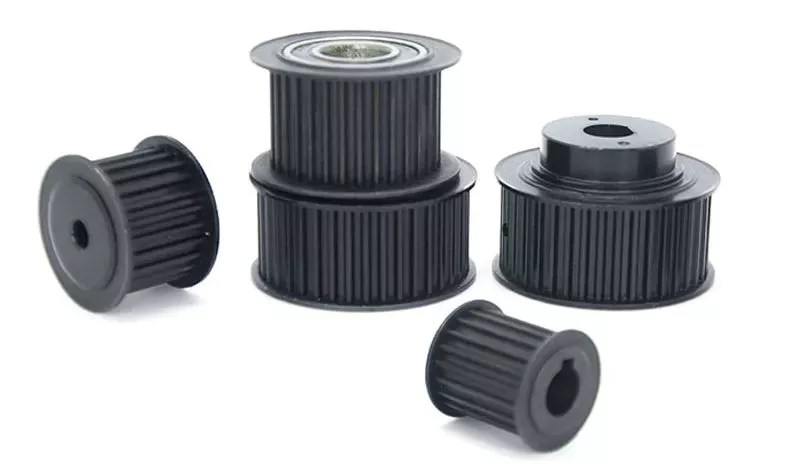
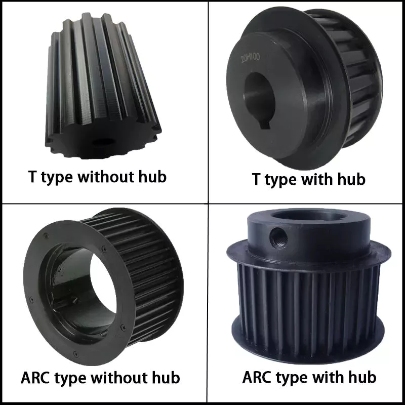
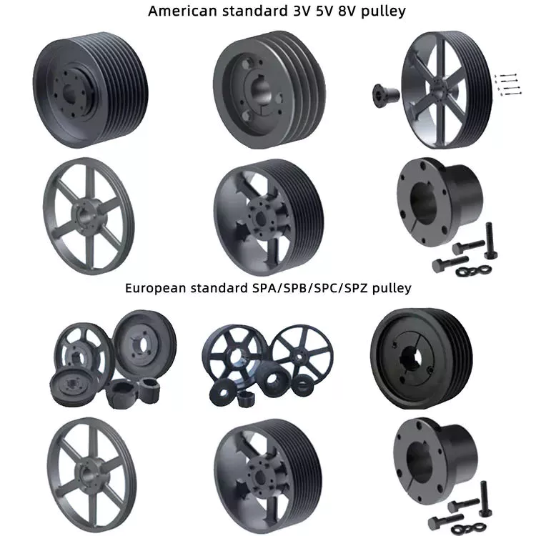
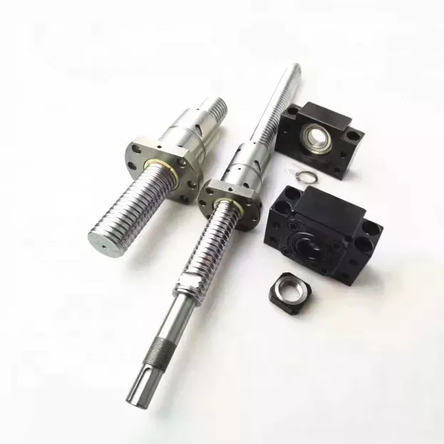
China Hot Manufacturing Custom Agricultural Farm Embroidery Sewing Machine Parts manufacturer

Product Description

Hot manufacturing Custom agricultural farm embroidery sewing machine parts

*How to receive an online quotation?

  1. Please send us your 3D drawing/2D drawing for us to check all dimension
  2. Specify the required material, finish, quantity information in the email, we will handle it for you once receiving it soon!

Note: Workable 3D Drawing Formats: STEP/IGS/X_T/STL/SOLIDWORKS etc, 2D Drawing with PDF will do.

*Our advantage:
1. Over 15-year CNC machining experience.
2. Small order accepted for the beginning. MOQ 10pcs~100pcs affordable.
3. Sample orders can be finished from 7 to 15 days
4. Top-quality guaranteed by skilled workers, managing system and status of facilities.
5. Our sales team is all professional and all can speak English
6. Professional quality inspection before delivery

*What we can offer:

1).Material capabilities: Alunimum 6061/stainless steel/titanium/brass/steel/alloy/copper, etc.
The material supplier we are working together is famous domestic brands  (such as PMI Press metal, Chinalco (Hengmei Aluminum) the aluminum supplier for Apple/HUAWEI/Foxconn) with more reliable quality--the standards "GB" to ensure the consistent quality! Instead, those cheap and non-standard materials that will kill our quality, double our machining work and production cost if something goes wrong, and delay the lead time & the best time of the customer to launch their product in the market, so when you choose the cheaper quotation, which takes this risk, please consider carefully 🙂

2).Quality control:
*We have specialized QC testers to check the quality of the products according to different customers' requirement. Usually, it's random inspection, and we also offer 100% inspection at a reasonable price if required.
*We have IQC to check the dimensions and surface of the incoming material
*We have PQC to inspect full-course during the manufacturing processing
*We have FQC to inspect all the anodizing/plating and other finishes' products from our supplier and proceed with the professional quality and appearance inspection before shipping.

3).Surface Finish:anodized finish/ coating/polish/ Passivation/ PVD finish/Plating/brush/heat treatment/fine glass beads/grounding/tumbled finish , etc.

4). Payment terms: T/T payment. The Sample order paid by full payment; Mass production with order amount exceeding can be paid a 50% deposit before production, and balance payment before shipping.

5).Production time: Usually it takes 5~10 working days for sample production; 15~20 working days for mass production days, it depends on your design, simple parts can be produced quickly, the complicated design parts would take us more machining time.

6).Machining capability: 30 sets of the most technologically advanced machining CNC milling machines, 20 sets of CNC turning machines, 25 sets of Multi-Spindle Japan Precision Swiss CNC lathes, and 4 sets of 2D &3D CMM (image measuring instrument) quality control equipment 3 QC staff, enabling CNC Manufacturing to deliver precise parts within the tightest of tolerances, ensuring the highest quality results to meet different customers' requirements.

7). Tolerance: +/- 0.02mm (for Metal shaft), +/-0.03mm ( for plastic), for special tolerance requirements, please point them out in the email, we will check if it's feasible to make it after studying it.

8).Shipping way:
1) 0-100kg: express&air freight priority,
2) >100kg: sea freight priority,
3) As per customized specifications

9). Packing & Delivery:

1.Packing Detail: Each product packed with plastic preservative, EPE, foam plastic bag, Carton outside, wood case or iron case or as per the customer's special requirement. Besides, the custom package takes a week to prepare in advance.

2.Delivery Detail: the fast International Shipping time takes 3 ~5 working days by DHL/UPS/FedEx, slow shipping time takes 7~ 8 working days by DHL/UPS/FedEx/TNT, etc.

*What the customers comments:

Remark: The products and pictures showed above are only to present the scope of our manufacturing types. We're happy to evaluate if we could custom the parts according to your drawings or samples after receiving them.

Send us an email now if any inquiry!


After-sales Service: Email Us Anytime If Any Problems
Warranty: Email Us Anytime If Any Requirements
Condition: New
Certification: CE, RoHS, GS, ISO9001
Standard: DIN, CE, RoHS, GS, ISO9001, GB, En, API650, China GB Code, JIS Code, Tema, ASME, Custom Machining
Customized: Customized

###

Samples:
US$ 200/Piece
1 Piece(Min.Order)

|
Request Sample

###

Customization:

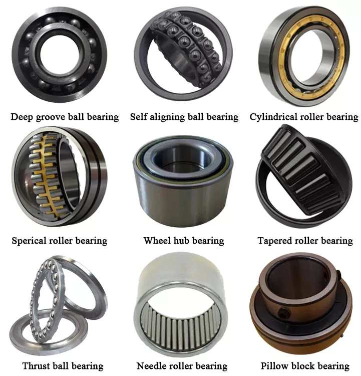
Types of Ball Bearings

In their most basic form, Ball Bearings have one common feature - they are made of steel. The majority of these bearings are made of 52100 steel, which has one percent chromium and one percent carbon. The steel can be hardened by heat trea
tment. 440C stainless steel is used for rusting problems. A cage around the ball balls is traditionally made from thin steel. However, some bearings use molded plastic cages to save money and friction.
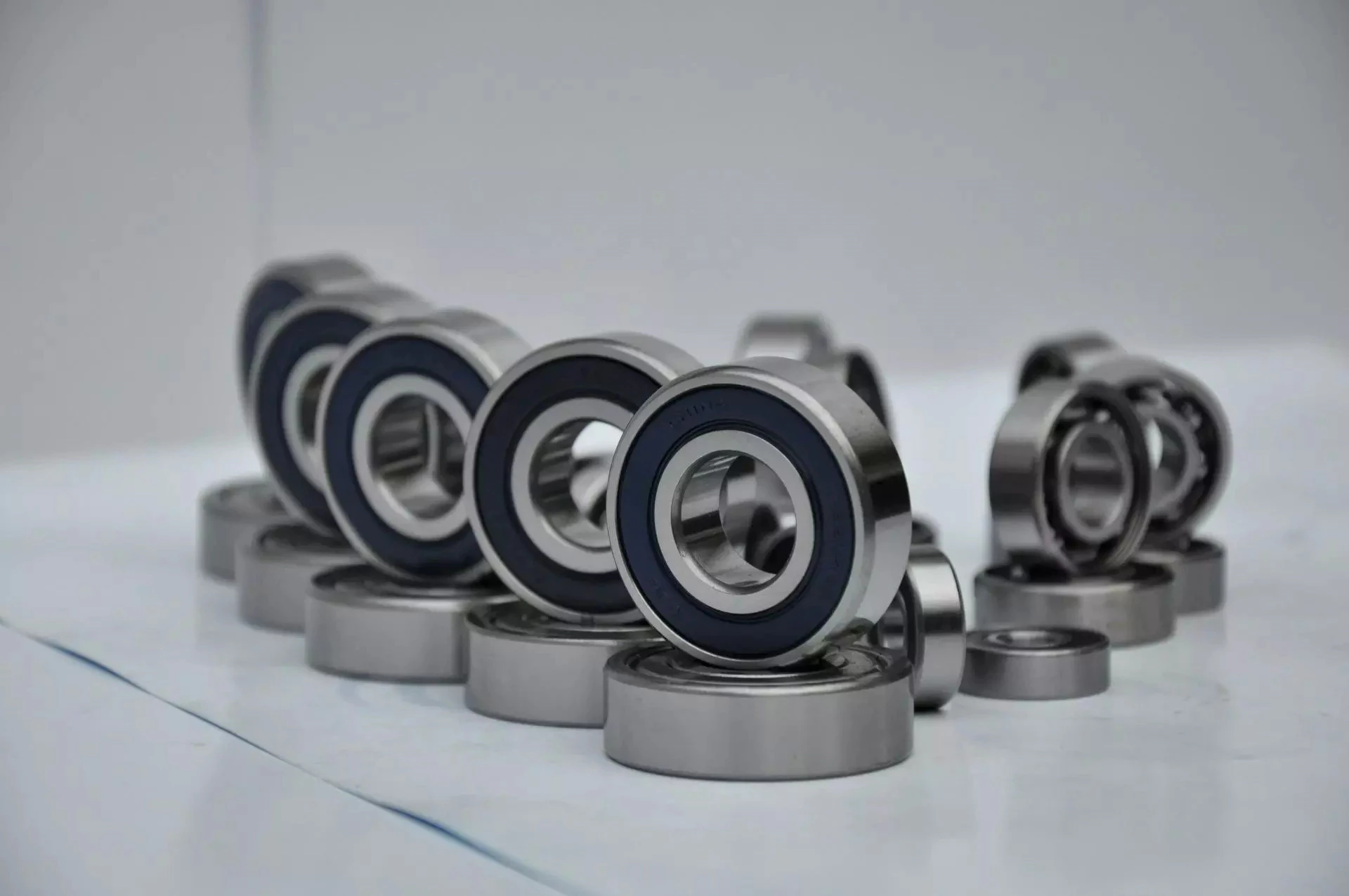
bearing

Single-row designs

Steel linear translation stages often use single-row designs for ball bearings. These types of bearings provide smooth linear travel and can withstand high loads. The material steel has a high modulus of elasticity and a high stiffness, as well as a lower thermal expansion than aluminum. For these reasons, steel is the material of choice for a ball bearing in a typical user environment. Single-row designs for ball bearings are also suitable for applications in humid or corrosive environments.
Single-row designs for ball bearings are available in a variety of sizes and are axially adjustable. They have a high radial capacity, but require relatively little space. Single-row deep groove ball bearings with snap rings are STN 02 4605 or R47, respectively. Bearings with snap rings are identified by a suffix such as NR. They may not have seals or shields installed.
These single-row angular contact ball bearings are capable of supporting axial and radial loads. In a two-raceway arrangement, the radial load on bearing A causes a radial load to act on bearing B. Both axial and radial forces are transmitted between single-row angular contact ball bearings, and the resulting internal force must be taken into account to calculate equivalent dynamic bearing loads P.
Single-row deep groove ball bearings are the most common type of ball bearings. These bearings are designed with only one row of rolling elements. The single-row design is simple and durable, which makes it ideal for high-speed applications. Single-row designs for ball bearings are also available in various bore sizes. They can also come in a variety of shapes and are non-separable. If you need a high-speed bearing, you may want to opt for a double-row design.
In addition to single-row designs for ball bearings, you can choose ceramic or steel ball bearings. Ceramic balls are considerably harder than steel balls, but they are not as hard as steel. Hence, ceramic bearings are stiffer than steel ball bearings, resulting in increased stress on the outer race groove and lower load capacity. This is a great benefit for those who need the bearings to be lightweight and strong.
The difference between single-row and double-row designs is in the way that the inner and outer ring are installed. A single-row design places the inner ring in an eccentric position relative to the outer ring. The two rings are in contact at one point, which causes a large gap in the bearing. The balls are then inserted through the gap. As a result, the balls are evenly distributed throughout the bearing, which forces the inner and outer rings to become concentric.
Deep-groove ball bearings are one of the most popular types of ball bearings. They are available in different designs, including snap-ring, seal and shield arrangements. The race diameter of a deep-groove ball bearing is close to the ball's diameter. These types of bearings are suited for heavy loads, and their axial and radial support are excellent. Their main drawback is that the contact angle cannot be adjusted to accommodate a wide range of relative loads.
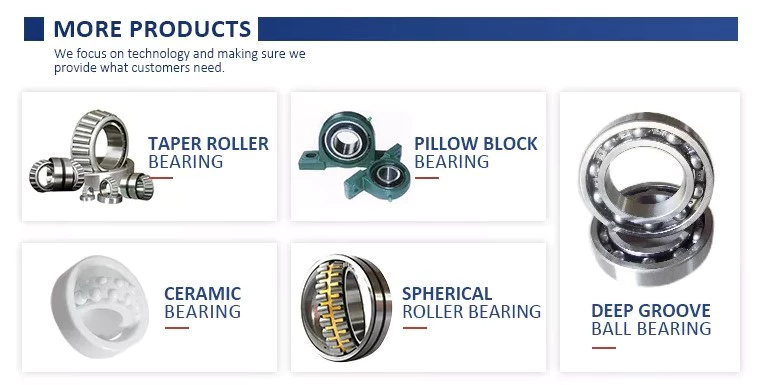
bearing

Ceramic hybrid ball bearings

Hybrid ball bearings with ceramic balls have numerous advantages. They feature improved kinematic behavior and require less lubrication. Consequently, they can reduce operating costs. Additionally, their low thermal expansion coefficient allows for smaller changes in contact angle and preload variations, and they can retain tolerances. Furthermore, ceramic hybrid ball bearings have significantly increased life spans compared to conventional steel-steel ball bearings, with up to 10 times the lifespan.
Although ceramic bearings can be used in automotive applications, many people believe that they're a poor choice for bicycle hubs. They don't reduce weight and only work well in high-rpm environments. As a result, many cyclists don't even bother with ceramic-based bearings. However, both Paul Lew and Alan are of the opinion that ceramic bearings are best suited for industrial or medical equipment applications. Furthermore, Paul and Alan believe that they are ideal for high-altitude drone motors.
Another advantage of ceramic hybrid ball bearings is that they use less friction than conventional steel-based balls. They are also more durable, requiring less lubrication than steel-based bearings. Furthermore, the lower friction and rolling resistance associated with ceramic-based ball bearings means that they can last ten times longer than steel-based bearings. A ceramic-based hybrid ball bearing can be used for applications where speed and lubrication are critical.
Ceramic hybrid ball bearings feature both steel and silicon nitride balls. Silicon nitride balls have 50% more modulus of elasticity than steel balls and can improve accuracy and precision. Ceramic balls also have a smoother surface finish than steel balls, which reduces vibration and spindle deflection. These benefits result in increased speed and improved production quality. In addition to this, ceramic balls can also reduce the operating temperature, enhancing the work environment.
Hybrid bearings are a popular alternative to steel bearings. They have some benefits over traditional steel bearings, and are becoming a popular choice for engineered applications. Hybrid bearings are ideal for high speed machines. The material used to manufacture ceramic balls is a high-quality alloy, and is comparatively inexpensive. But you must understand that lubrication is still necessary for hybrid bearings. If you are not careful, you may end up wasting money.
These ball bearings can be used in many industries and applications, and they are widely compatible with most metals. The main advantage of hybrid ball bearings is that they are very durable. While steel balls tend to corrode and wear out, ceramic ball bearings can withstand these conditions while minimizing maintenance and replacement costs. The benefits of hybrid ball bearings are clear. So, consider switching to these newer types of ball bearings.
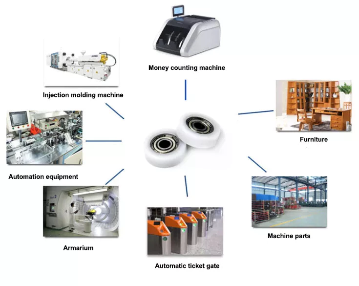
bearing

Self-aligning ball bearings

Self-aligning ball bearings are a good choice for many applications. They are a great alternative to traditional ball bearings, and they are ideal for rotating applications in which the shaft must move in several directions. They are also ideal for use in rotating parts where a tight tolerance is necessary. You can choose between two types: plain and flex shaft. Read on to find out which one will suit your needs.
Self-aligning ball bearings are designed with a higher axial load carrying capacity than single-row radial deep groove ball bearings. The amount of axial load carrying capacity is dependent upon the pressure angle. These bearings have a hollow raceway in the outer ring that allows the inner ring to pivot without friction. They are often used for high-speed applications. Because of their design, they are highly accurate.
Self-aligning ball bearings are radial bearings that feature two rows of balls in a spherical outer ring. They also feature two deep uninterrupted raceway grooves in the inner ring. Their unique features make them an excellent choice for applications where shaft deflection is a significant factor. Despite their small size, they have a high level of precision and can withstand heavy loads.
Self-aligning ball bearings can compensate for misalignment in shaft applications. The inner ring and ball assembly are positioned inside an outer ring containing a curved raceway. This spherical design allows the balls and cage to deflect and re-align around the bearing center. These bearings are also ideal for applications where shaft deflection is significant, such as in simple woodworking machinery.
Another type of self-aligning ball bearing uses a common concave outer race. Both balls and outer races automatically compensate for angular misalignment caused by machining, assembly, and deflections. Compared to spherical rollers, they have lower frictional losses than their spherical counterparts. Self-alignment ball bearings also have lower vibration levels compared to other types of bearings.
Self-aligning ball bearings operate in misaligned applications because their spherical outer raceway can accommodate misalignment. This design allows them to work in applications where shaft deflection or housing deformation is common. They are therefore more suitable for low to medium-sized loads. The only real drawback to self-aligning ball bearings is their price. If you need to purchase a self-aligning ball bearing for your next project, you can expect to pay around $1500.

China Hot Manufacturing Custom Agricultural Farm Embroidery Sewing Machine Parts     manufacturer China Hot Manufacturing Custom Agricultural Farm Embroidery Sewing Machine Parts     manufacturer
editor by czh 2022-11-27

China Die Casting Aluminum Agricultural Machine Parts agricultural spare parts

Product Description

HangZhou XIHU (WEST LAKE) DIS. CZPT METAL PRODUCT FACTORY was established in 2001.;  BOLANG centres high precision CNC machining as our core competence,; the company specializes in producing auto parts,; agriculture parts,; machinery parts,; lighting parts,; hardware fittings etc.; We can provide pressure casting,; sand casting,; investment casting,; gravity casting,; the material covers aluminum alloy such as A380,; A390,; ADC12,;YL102,; A356,; aluminum extrusion of 6000 series,; zinc alloy,; iron,; copper etc.;

The products are mainly exported to countries such as USA,; Europe (England,; Germany,; Italy,; Belgium etc);,; Asia (Japan,;Korea etc);.; And the company has successfully passed ISO/TS16949 quality management certificate.;
 

Material:;  ADC-12
Cavity Number:; 1
Process Technology:; High pressure die casting
Product Dimensions:;  Customized
Casting General Tolerance:; Grade GB-CT4
Surface Finish:;  Polishing,; Vibratory deburring,;Anodizing,; Power Coating,; Painting,;etc
Flow Processes:;  Die casting,; Trimming,; Polishing,; vibratory deburring,; Machining,; Cleaning,;Packing,; Shipping
Control Measure:; Incoming Material Test,; First Article inspection,; Routing inspection,; Final item inspection,;  and Outgoing quality control
Inspection Equipment:;  CMM,; Caliper,; Plug Gage,;Spectrograph,;Pneumatic measuring tool,;etc
Application:;  LED Lighting Accessories Furniture Accessories  Electronic & Electric Accessories  Auto & Motorcycle Accessories Machinery Accessories  Public Facilities  
Certificate:; ISO/TS16949:;2009
Lead Time 30-35 days
Trade Term:; FOB HangZhou


FAQ
Q1.; When can I get the price?
A:;  We usually quote within 2-3 days after we receive the RFQ or feedback within 2 days if any questions on prints need to be confirmed.;
Q2.; How long is the lead-time for mold?
A:;  Usually it depends on the size and complexity of the mold.; But normally,; the lead time is 35-45days.; 
Q3.; I have no 3D drawing,; how should I start the new project?
A:;  You can supply us a sample,; we will help work on establishing 3D model accordingly.;
Q4.; Before shipment,; how to ensure the products quality?
A:; We have strict development procedure,; during samples development,; we have capacity to produce according to PPA,; after PSW approved,;


Die Casting Machine Type: Cold Chamber Die Casting Machine
Die Casting Method: Vacuum Die Casting
Application: Electronic Accessories
Machining: CNC Machining
Material: Aluminum
Surface Preparation: Spray Coating

###

Customization:

###

Material:  ADC-12
Cavity Number: 1
Process Technology: High pressure die casting
Product Dimensions:  Customized
Casting General Tolerance: Grade GB-CT4
Surface Finish:  Polishing, Vibratory deburring,Anodizing, Power Coating, Painting,etc
Flow Processes:  Die casting, Trimming, Polishing, vibratory deburring, Machining, Cleaning,Packing, Shipping
Control Measure: Incoming Material Test, First Article inspection, Routing inspection, Final item inspection,  and Outgoing quality control
Inspection Equipment:  CMM, Caliper, Plug Gage,Spectrograph,Pneumatic measuring tool,etc
Application:  LED Lighting Accessories Furniture Accessories  Electronic & Electric Accessories  Auto & Motorcycle Accessories Machinery Accessories  Public Facilities  
Certificate: ISO/TS16949:2009
Lead Time 30-35 days
Trade Term: FOB Ningbo

###

FAQ
Q1. When can I get the price?
A:  We usually quote within 2-3 days after we receive the RFQ or feedback within 2 days if any questions on prints need to be confirmed.
Q2. How long is the lead-time for mold?
A:  Usually it depends on the size and complexity of the mold. But normally, the lead time is 35-45days. 
Q3. I have no 3D drawing, how should I start the new project?
A:  You can supply us a sample, we will help work on establishing 3D model accordingly.
Q4. Before shipment, how to ensure the products quality?
A: We have strict development procedure, during samples development, we have capacity to produce according to PPA, after PSW approved,

The Mechanical Advantage of a Pulley

A pulley is an important tool for many tasks. The advantage that it offers over a hand-held mechanism is its mechanical advantage. In this article, we'll discuss the types of pulleys and their applications. We'll also look at the types of compound pulleys. And, of course, there's a little bit about the mechanical advantage of a pulley. This article will help you decide whether this tool is right for your needs.
pulley

Mechanical advantage of a pulley

A pulley has a mechanical advantage over a lever because it is able to produce more force over longer distances. The mechanical advantage of a pulley sounds brilliant and could produce energy. But what exactly is this mechanical advantage? Let's take a look. First, consider how a pulley works. A rope supports a 100kg mass, which requires 500 newtons of force to lift. If the rope supports a 100kg mass, two sections of rope can support that load. Using a pulley, you can lift the same weight with half the force.
A pulley's ideal mechanical advantage is the ratio of the force applied to the total length of the rope. The larger the radius, the greater the mechanical advantage. A pulley made up of four rope segments has an ideal mechanical advantage of four. Therefore, a four-segment pulley would multiply the force applied by four. As the numbers on the rope segments are smaller than the total length of the rope, it would be better to use a compound pulley.
The mechanical advantage of a pulley can be calculated by using the T-method. The first step in calculating the mechanical advantage of a pulley is defining the force you need to lift. Then, divide that force by two to calculate the amount of force you need to lift the load. Once you know this amount, you can design a pulley to meet your needs. That way, you can achieve the perfect balance between the two types of pulleys.

Types of pulleys

The main function of the pulley is to change the direction of the force. The mechanical advantages of a single pulley are two. Ideally, two pulleys should have two or more mechanical advantages. The mechanical advantage of compound pulleys can be increased to two or more. The number of pulleys that make up the composite pulley will determine the mechanical advantage. Certain types of pulleys are combined in one housing.
A stepped pulley is a set of pulleys with stepped surfaces. Each face is anchored to the mid-axis in an ordered sequence. This design gives these pulleys their name. They are used to increase and decrease the speed of the driven pulley. Step pulleys are usually used in pairs. They can be straight or stepped, but usually come in pairs.
The three main types of pulleys are pulleys, rope pulleys, and chain pulleys. Pulley Pulley systems use mechanics to lift and lower heavy objects. The Greek historian Plutarch credits the invention of the pulley to Archimedes of ancient Sicily. The Mesopotamians used rope pulleys to lift water around 1500 BC, and Stonehenge is said to have been built using a rope pulley system.
pulley

Application of pulley system

The advantages of using a pulley system are numerous. The ability to lift heavy objects is a good example. The pulley system makes it easy for people to lift blocks and other large objects. It can be used in many different applications, from utility elevators to construction cranes. In addition, it is widely used on sailing boats. If you want to learn more about the benefits of a pulley system, keep reading!
You can use the pulley system to water flowers or water plants. Some of them even lowered the pot to make cleaning easier. Pendant lights are another great place to install a pulley system. Climbing and fishing are just some of the activities that utilize the pulley. They are great for fishing and gardening. And since they are so versatile, you can use the pulley system anywhere.
To get the most out of your pulley system, you must choose a product that has all of the above attributes. A high-quality pulley must have a large pulley diameter and be made of sturdy materials. The cables must also be properly supported in the pulleys to ensure a long service life for your investment. A good cable should have minimal cracks and be lubricated. These factors are the most important considerations when choosing a pulley system for your needs.

composite pulley

Composite pulley systems combine two or more movable pulleys. These systems maximize the force to move the weight and can also change direction so they can be used to lift weights. Composite pulley systems can be as simple or as complex as your needs. For example, a pulley pulley system uses multiple pulleys on each axis. This method is often used for hoisting building materials.
A compound pulley system has two or more rope segments, each of which is pulled up on a load. It can increase lift by making objects move faster. These systems are common on large sailboats and construction sites. Composite pulleys are also available for larger boats. Due to their versatility, they are versatile tools for construction sites and large sailboats. If you have their app, you should consider buying one.
The main advantage of composite pulleys is their versatility. You can use them to lift weights or use them to save energy. Composite pulleys are especially useful for lifting heavy objects. For example, you can tie a paper clip to the end of the rope and pull it up. The flag is then lifted into the air with the help of compound pulleys. Composite pulleys are a great invention and they are often used in construction.

security considerations

There are several safety considerations to consider when using pulleys. The first is Secure Workload (SWL). This value is a general guideline for the maximum weight a pulley can safely handle. It varies according to the height and angle of the pulley. Besides SWL, there are some other factors to consider. Consider each one before deciding on the pulley that best suits your needs.
Another safety consideration is the weight of the load. Since the highs of the pulley are higher than the lows, it doubles in weight. The weight of the high point should not exceed 4 kN. The safety factor is calculated by multiplying the strength of the pulley by the weight of the load. Secondary COD has a safety factor of 10:1 and bulletproof primary anchors should be used with pulleys.
If using a chain hoist, you must be trained in the appropriate type of lifting. It is important not to hang on the top hooks of the structure, nor to overload or rig the hooks with multiple slings. You should also avoid corroded or damaged chains, as they can cause the crane to jam or overload. A worn chain can even cause the load to drop.
pulley

Components of a pulley system

Proper design of the pulley system can increase the life of the cables and pulleys. Larger diameter cables should be selected as they are more durable than smaller diameter cables. The cables should also be supported in the pulley grooves. The pulley must be designed to be compatible with the cable and its lubrication should be optimal. Proper lubrication of cables and pulleys will ensure maximum durability and longevity.
The first type of pulley is called a fast pulley. These pulleys are used for quick start and stop of the machine. These pulleys are usually mounted in pairs on the countershaft of the machine. One pulley is tightly mounted on the machine shaft, while the other pulley is fitted with a free-spinning mechanism. When the machine is running, the belt is mounted on the tensioner pulley, and when it is stopped, the belt slides on the independent pulley.
Composite pulley sets reduce the overall effort required by reducing the size of the pulley. These are usually attributed to Archimedes. Flat pulleys are often used in flat belt driven transmission systems. These are used in high-speed, low-power applications. Flat pulley idlers are also used on the back of traditional V-belts.

China Die Casting Aluminum Agricultural Machine Parts     agricultural spare partsChina Die Casting Aluminum Agricultural Machine Parts     agricultural spare parts
editor by czh 2022-11-26

China Construction Machinery/Agricultural Machinery/Vehicles/Valve Alloys/Aluminum/Stainless Steel Forged Parts agricultural trailer brake parts

Product Description

Aluminum Alloy Product description
Machining of parts can be completed by CNC precision machine tool. We have more than 20 sets CNC equipments available, with 2 million production value each month. With the drawings offered by customer and the result of graphic processing program, proper engagement of cutting edge and feed value will be given for precise cutting. 
Parts of aluminum ally are subject to surface treatment.  Adhesive blasting method can help make parts more abrasive. Rigidity on surface of parts can be increased by use of anodic oxidation. Remaining 60 degree rigidity on parts plays an important role in keeping them from being abraded. With anodic oxidation method, oxide film reaches the thickness up to 0.2mm and has rust protection and anti-oxidative functions. Attached to various colors,  anodic oxidation can be made many different colors for surface of parts such as light black, muted black, golden yellow, blue and etc. Bright black is common 1 required for instruments and apparatus as well as mechanical equipments. Muted black is 1 color frequently used for optical instruments, film and television equipments and medical instruments and apparatus. Palm print apparatus consists of precision parts of aluminum alloy which are CZPT blasting and anodic oxidation featuring muted color which is not reflective and no disturbance caused.
Aluminum Alloy parts Support customization
We choose aluminum alloy materials such as 5052,6061,7075 that are found in conformity with international standard based on customer's requirements. All aluminum materials are subject to ageing treatment, guaranteeing there is no deformation happening during the machining operation and in the course of usage.  

Processing procedure is strictly controlled. First of all, CNC is required to process the shape and when data reaches standard, CNC processes hollow part. When CNC works, it is critical to choose a proper milling cutter. Coated milling cutter features sharp and wear resistance. In the course of cutting, factors such as feed and cutting depth affects quality and form and location tolerance. In the process of processing aluminum alloy, deformation appeared in parts is a knotty problem. Whether processing procedure is correct or not is a significant factor affecting product process. A technology, called surface sand blasting, can remove de-burring left. During the sand blasting, pressure for air under compressed condition shall not be higher, which the reasonable range is 0.5-0.6MP. Sand blasts too light if air pressure is high and parts is inclined to be deformed if air pressure is high. Hard anodized ensure the normal level of Rockwell hardness for metal surface.

The company was established in February 2007, located in cHangZhou district, HangZhou city.We mainly

manufacture all kinds of mask production equipment, plane mask machine and KN95 machine.It also

produces injection and stamping CZPT and customized automatic production equipment.Business,

technology, production, administration a total of 30 people.Processing equipment, testing equipment a total

of more than 40 .The company has strict quality management in accordance with ISO9000.

Q1:What's kinds of information you need for quotation?
VMT: You can provide 2D/3D drawing or send your sample to our factory, then we can make according to your sample.

Q2: Can we sign NDA?
VMT: Sure. We never divulge customers' information to anyone else.

Q3: Do you provide sample?  
VMT: Yes, we can provide you sample before mass order.

Q4: How can you ensure the quality?
VMT: We have profesional QC department to guarantee the quality.


US $0.5-5
/ Piece
|
100 Pieces

(Min. Order)

###

After-sales Service: 1 Year
Warranty: 1 Year
Condition: New
Certification: CE, ISO9001
Standard: GB, JIS
Customized: Customized

###

Customization:

###

Aluminum Alloy Product description
Machining of parts can be completed by CNC precision machine tool. We have more than 20 sets CNC equipments available, with 2 million production value each month. With the drawings offered by customer and the result of graphic processing program, proper engagement of cutting edge and feed value will be given for precise cutting. 
Parts of aluminum ally are subject to surface treatment.  Adhesive blasting method can help make parts more abrasive. Rigidity on surface of parts can be increased by use of anodic oxidation. Remaining 60 degree rigidity on parts plays an important role in keeping them from being abraded. With anodic oxidation method, oxide film reaches the thickness up to 0.2mm and has rust protection and anti-oxidative functions. Attached to various colors,  anodic oxidation can be made many different colors for surface of parts such as light black, muted black, golden yellow, blue and etc. Bright black is common one required for instruments and apparatus as well as mechanical equipments. Muted black is one color frequently used for optical instruments, film and television equipments and medical instruments and apparatus. Palm print apparatus consists of precision parts of aluminum alloy which are abrasive blasting and anodic oxidation featuring muted color which is not reflective and no disturbance caused.
Aluminum Alloy parts Support customization
We choose aluminum alloy materials such as 5052,6061,7075 that are found in conformity with international standard based on customer's requirements. All aluminum materials are subject to ageing treatment, guaranteeing there is no deformation happening during the machining operation and in the course of usage.  

###

Processing procedure is strictly controlled. First of all, CNC is required to process the shape and when data reaches standard, CNC processes hollow part. When CNC works, it is critical to choose a proper milling cutter. Coated milling cutter features sharp and wear resistance. In the course of cutting, factors such as feed and cutting depth affects quality and form and location tolerance. In the process of processing aluminum alloy, deformation appeared in parts is a knotty problem. Whether processing procedure is correct or not is a significant factor affecting product process. A technology, called surface sand blasting, can remove de-burring left. During the sand blasting, pressure for air under compressed condition shall not be higher, which the reasonable range is 0.5-0.6MP. Sand blasts too light if air pressure is high and parts is inclined to be deformed if air pressure is high. Hard anodized ensure the normal level of Rockwell hardness for metal surface.

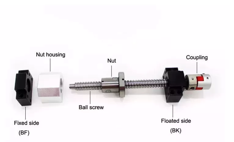
Advantages of Ball Screws and How They Can Benefit Your Applications

When selecting a ball screw for your application, there are several factors to consider. This article will discuss high mechanical efficiency, low friction, multiple repair options, and application requirements. Choosing the right ball screw can help you get the job done quickly and effectively. To make your decision easier, consider the following tips. Read on to learn about some of the advantages of ball screws and how they can benefit your applications. Here are some of the most common types:
air-compressor

High mechanical efficiency

The mechanical efficiency of ball screws can be measured using the axial load test. The axial load is equal to 0.5 x FPr / 2Fpr. The elastic deformations are measured as DL1 and DL2, respectively. Common engineering procedures work at 90 percent reliability; however, certain sectors require higher reliability, which has a direct impact on the dynamic load capacity. The axial load test is one of the most widely used methods to determine the mechanical efficiency of ball screws.
In order to achieve high translation, ball screws must be designed with high stiffness and positioning accuracy. In addition, high preloads increase the initial driving torque and cause more friction and heat. Other important design criteria include low driving torque and reduced slip motion. This means that the high translation capacity of ball screws must be well matched to the overall application. The following are some common design criteria for ball screws. You can select the best type of ball screw for your needs.
The high mechanical efficiency of ball screw is achieved by avoiding the common sag and pitch problem. The ball track design helps to reduce the centrifugal force. The ball screw's diameter can be adjusted by adjusting the centre pitch of the nut on two ball tracks. The nut's axial load is also adjusted through the offset centre pitch. This method allows the users to increase the mechanical efficiency of ball screw by up to 40%.
When calculating the mechanical efficiency of ball screw, consider the application's environment, speed, and other factors. If the application requires precision and accuracy, then the ball screw is the right choice. The engineering department of a ball screw manufacturer will carefully review the application factors and come up with a design that meets the application's expectations. Moreover, some manufacturers even offer customized ball screws, which can be tailored to your requirements.

Low friction

The operating performance of a low-friction ball screw is characterized by its minimal friction. This screw has a structure that transmits forces through rolling steel balls. The torque is calculated by calculating the load and the lead screw's dimensions. This type of screw can be used for a variety of different applications, including hydraulic systems. Read on to learn more about this type of screw and how it can help you build a more reliable and durable car.
The critical speed of a ball screw is higher than that of a lead screw, so this type of screw can accommodate larger loads and speeds. It also has a lower friction coefficient, which reduces the amount of heat produced. High-quality ball screws can withstand longer duty cycles than standard lead screws. However, in order to compare the two, you must take into account the duty cycle. Low-friction ball screws are more durable than lead screws, and the duty cycle is only one of the factors you should consider when selecting them.
The ball bearings are the most prominent component of a low-friction ball screw. Their main function is to reduce the friction between the nut and the shaft. Without them, the friction would be too high. This feature is possible thanks to the ball bearing's groove profile. Two arcs intersect at the contact points on the shaft and nut. Consequently, the ball bearing reduces friction in a way that is essentially non-existent without the bearing.
The mechanical efficiency of a low-friction ball screw is very high. The typical ball screw is up to 90% efficient, but some types can reach a higher efficiency. They are commonly used in machine slides, presses, and linear actuators. The high efficiency of a low-friction ball screw makes it a great choice for many different applications. This type of screw is made of several main components. The ball bearings provide the helical raceway for the ball assembly and threaded shaft is the screw part. The ball screw is comparatively more bulky than a conventional leadscrew, but the overall size is smaller than its lead counterpart.
air-compressor

Multiple repair options

A damaged ball screw will typically display visible physical signs, including noise or vibration. Additionally, worn ball screws will require more horsepower and torque to operate. They may also cause lead accuracy issues. Luckily, there are multiple repair options for ball screws. You can get new ball screws to restore preload and reduce backlash. But there are some warning signs to look out for first. Keeping a close eye on your ball screw's health can help you avoid a costly replacement.
Look for a ball screw repair company with a proven track record of servicing all types of ball screws. The service should offer a free evaluation and three types of service: reload, recondition, and replacement. Reload is the simplest option and involves cleaning and polishing the screw and ball nut. Reconditioning or replacement, on the other hand, requires new parts. Choose the one that offers the best value for your money.
EP offers an emergency service and superior service for your ball screws. Their UK service includes delivery and international shipping. All ballscrew repairs are covered by a full service warranty, and the company is known for providing competitive pricing. If you do need a ball screw repair, look no further. Contact K+S today to discuss your specific needs. You'll be glad you did. You'll save up to 70% over purchasing a new ball screw.
While ball screw repair is an easy and inexpensive option, it may be necessary to have it replaced more frequently than the usual. In addition to replacing worn ball screws, you may need to consider a different type of repair. This process involves grinding the ball nut and journal diameters back to their original size. Fortunately, level 4 is the most expensive but can restore a screw's lifespan. This is also the most extensive type of repair available for a ball screw.

Application requirements

A ball screw is an efficient solution for precision motion control in many applications, including automotive and aerospace. These screw-type devices are highly resistant to corrosion, and the alternating steel-ceramic architecture ensures extreme reliability and sturdiness. For the aerospace sector, a ball screw replaces the typical hydraulic system, and the product is used in wind turbine blade pitch and directional position, solar panel movement, and gate control in hydroelectric stations. Ball screws are also used in motorised inspection tables, step photolithography machines, microscopic integrated circuits, and many other applications.
The most critical requirements for a ball screw assembly are backlash and bearing support. Backlash is the amount of axial motion between the screw and nut, which leads to positioning errors. Although this axial motion is minimal, it can be as little as 70um. If the preload is too large, a ball screw may suffer from excessive heat. Depending on the application, the amount of preload required can be adjusted to maximize the overall performance of the device.
The choice of screw is determined by the load capacity. For example, plastic nuts are commonly used for light loads, while bronze nuts are used for loads that weigh several thousand pounds. Lead screws are not particularly reliable in situations where load requirements are extremely high, and a ball screw will often be a better option. The lower friction of a ball screw allows it to withstand higher duty cycles than a lead screw. When the load requirements exceed lead screws' capacity, a ball screw is the better choice.
A step photolithography machine is another example of an application where ball screws play an important role. This device helps manufacturers produce microscopic integrated circuits by harnessing the reaction of light. A stepper is a critical piece of this machine, as it controls the positioning of light exposure on the silicon wafer. High precision is required for this application. Ultimately, a ball screw will make the process easier. Its proven record for meeting instrumentation requirements is an excellent example of its value in the laboratory.
air-compressor

Cost

The global market for ball screws is growing at a steady pace, but what drives the growth? In the ball screw industry, performance, cost, and analytical predictability are the primary concerns of OEMs. This market study provides in-depth analysis of these market dynamics. You'll learn how to best compete in the global market for ball screws. Here are some tips to help you get started:
Ensure you have a good grasp of the differences between lead and ball screws. The cost of lead screws depends on their efficiency, and some of them can achieve C5 level accuracy. However, ball screws are more durable and more repeatable. Besides, lead screws can't achieve high precision because of their sliding motion, which gradually grinds away the accuracy. As a result, the cost of a ball screw is more than compensated by the improved performance of OEMs.
To get the best price for ball screw, look for a manufacturer with a strong technical force. Most of these manufacturers have sophisticated equipment and strict quality control systems. They draw inspiration from the requirements of the market and have continuously increased their technological content to stay ahead of the competition. If you're in Pune, look for a manufacturer with this technology. It won't be difficult to do business with such a supplier. The company will also provide you with contact information, including their office address and phone numbers.
When choosing between lead and ball screws, you need to understand how they work and why they're more reliable. Ball screws are more durable than lead screws, which is one of the primary reasons for their popularity. Lead screws, on the other hand, are often used for vertical applications. Lead screws tend to be cheaper than ball screws, but they have more limitations. When used properly, however, they can increase the life and performance of machines. In general, they're corrosion-resistant and offer great design flexibility.

China Construction Machinery/Agricultural Machinery/Vehicles/Valve Alloys/Aluminum/Stainless Steel Forged Parts     agricultural trailer brake partsChina Construction Machinery/Agricultural Machinery/Vehicles/Valve Alloys/Aluminum/Stainless Steel Forged Parts     agricultural trailer brake parts
editor by czh 2022-11-25

China Agricultural Spare Parts Topink for Kubota L2808, L3408 Tractor with Great quality

Product Description

Agricultural spare parts Topink For CZPT L2808,L3408 Tractor

If you're in the market for a new toplink for your CZPT tractor, you've come to the right place. We'll cover everything you need to know: working length, pins, and Adjustable top links. Plus, we'll discuss how to install them. After all, no tractor can function without one! So, start shopping for a new toplink now! There are several benefits to doing so.
Adjustable top link
This adjustment kit will secure your category 1 CZPT tractor's three-point hitch. It features a 15 degree pivot angle and 4 inches of travel on either end. The attachment includes a tilting trailer cart with a quick release lever for dumping. It has a 600-lb. capacity. If you're interested in purchasing this attachment for your tractor, visit your local CZPT dealer.
Working length
To get the right working length of your hydraulic top linkage, you need to measure the distance between the pins on the tractor and the implement. To determine this, you can use a ruler or a tape measure to measure the distance between the tractor and the implement. Then, measure the length again to ensure that the pins are the correct distance apart. A standard working length for a hydraulic top link is 15 feet.
Pins
To find the correct Topink For CZPT tractor pins, visit a retailer like Agriline Products Ltd. Agriline offers a range of
linkage parts, including pins, top links, lower links, link arms, stabilisers, chains, and drawbars. All products are backed by
excellent customer service. If you need a new set of pins for your tractor, contact us today.
Side links
There are several different ways to fix the problem. Using a pan filled with diesel and sticking it where the handle goes may
remove the dirt, while using a pressure washer will clean the area. You can also try electrolysis. However, this can take several weeks to complete. Hopefully, 1 of these solutions will work for you. If not, here are a few ideas to help you fix the problem:
Pins at tractor end
Topink pins at the tractor end are used for the top link arms, lower link arms, and lift arms. To replace a toplink pin, remove
the toplink arm and cross drill a new hole opposite to the old one. Topink pins at tractor end for CZPT tractor
Pins at implement end
The towing pin, leveling box, and hydraulic system are all controlled by the Pins at the implement end of a Topink For CZPT Tractor. Without the stabilizers, implements can flop back and forth, damaging the rear tires. Pins at the implement end of a Topink For CZPT Tractor are critical for a safe and stable work environment.
Pins at tractor
Whether you own a CZPT tractor or are plHangZhou to buy 1 for your neighbor, it can be useful to know the correct size of the pins for your tractors. There are several different pin sizes for tractors, which you can find on the tractor manual, or at the parts store. A small diameter pin will fit a compact tractor, while a larger diameter pin will fit a large tractor.

Company Information


US $9.99
/ Piece
|
1 Piece

(Min. Order)

###

Type: Agricultural
Usage: Agricultural Products Processing, Farmland Infrastructure, Tillage, Harvester, Planting and Fertilization, Grain Threshing, Cleaning and Drying
Material: Iron
Power Source: Electricity
Weight: 3.67kg
After-sales Service: Installation Guide 3-Year Warranty

Analytical Approaches to Estimating Contact Pressures in Spline Couplings

A spline coupling is a type of mechanical connection between two rotating shafts. It consists of two parts - a coupler and a coupling. Both parts have teeth which engage and transfer loads. However, spline couplings are typically over-dimensioned, which makes them susceptible to fatigue and static behavior. Wear phenomena can also cause the coupling to fail. For this reason, proper spline coupling design is essential for achieving optimum performance.
splineshaft

Modeling a spline coupling

Spline couplings are becoming increasingly popular in the aerospace industry, but they operate in a slightly misaligned state, causing both vibrations and damage to the contact surfaces. To solve this problem, this article offers analytical approaches for estimating the contact pressures in a spline coupling. Specifically, this article compares analytical approaches with pure numerical approaches to demonstrate the benefits of an analytical approach.
To model a spline coupling, first you create the knowledge base for the spline coupling. The knowledge base includes a large number of possible specification values, which are related to each other. If you modify one specification, it may lead to a warning for violating another. To make the design valid, you must create a spline coupling model that meets the specified specification values.
After you have modeled the geometry, you must enter the contact pressures of the two spline couplings. Then, you need to determine the position of the pitch circle of the spline. In Figure 2, the centre of the male coupling is superposed to that of the female spline. Then, you need to make sure that the alignment meshing distance of the two splines is the same.
Once you have the data you need to create a spline coupling model, you can begin by entering the specifications for the interface design. Once you have this data, you need to choose whether to optimize the internal spline or the external spline. You'll also need to specify the tooth friction coefficient, which is used to determine the stresses in the spline coupling model 20. You should also enter the pilot clearance, which is the clearance between the tip 186 of a tooth 32 on one spline and the feature on the mating spline.
After you have entered the desired specifications for the external spline, you can enter the parameters for the internal spline. For example, you can enter the outer diameter limit 154 of the major snap 54 and the minor snap 56 of the internal spline. The values of these parameters are displayed in color-coded boxes on the Spline Inputs and Configuration GUI screen 80. Once the parameters are entered, you'll be presented with a geometric representation of the spline coupling model 20.

Creating a spline coupling model 20

The spline coupling model 20 is created by a product model software program 10. The software validates the spline coupling model against a knowledge base of configuration-dependent specification constraints and relationships. This report is then input to the ANSYS stress analyzer program. It lists the spline coupling model 20's geometric configurations and specification values for each feature. The spline coupling model 20 is automatically recreated every time the configuration or performance specifications of the spline coupling model 20 are modified.
The spline coupling model 20 can be configured using the product model software program 10. A user specifies the axial length of the spline stack, which may be zero, or a fixed length. The user also enters a radial mating face 148, if any, and selects a pilot clearance specification value of 14.5 degrees or 30 degrees.
A user can then use the mouse 110 to modify the spline coupling model 20. The spline coupling knowledge base contains a large number of possible specification values and the spline coupling design rule. If the user tries to change a spline coupling model, the model will show a warning about a violation of another specification. In some cases, the modification may invalidate the design.
In the spline coupling model 20, the user enters additional performance requirement specifications. The user chooses the locations where maximum torque is transferred for the internal and external splines 38 and 40. The maximum torque transfer location is determined by the attachment configuration of the hardware to the shafts. Once this is selected, the user can click "Next" to save the model. A preview of the spline coupling model 20 is displayed.
The model 20 is a representation of a spline coupling. The spline specifications are entered in the order and arrangement as specified on the spline coupling model 20 GUI screen. Once the spline coupling specifications are entered, the product model software program 10 will incorporate them into the spline coupling model 20. This is the last step in spline coupling model creation.
splineshaft

Analysing a spline coupling model 20

An analysis of a spline coupling model consists of inputting its configuration and performance specifications. These specifications may be generated from another computer program. The product model software program 10 then uses its internal knowledge base of configuration dependent specification relationships and constraints to create a valid three-dimensional parametric model 20. This model contains information describing the number and types of spline teeth 32, snaps 34, and shoulder 36.
When you are analysing a spline coupling, the software program 10 will include default values for various specifications. The spline coupling model 20 comprises an internal spline 38 and an external spline 40. Each of the splines includes its own set of parameters, such as its depth, width, length, and radii. The external spline 40 will also contain its own set of parameters, such as its orientation.
Upon selecting these parameters, the software program will perform various analyses on the spline coupling model 20. The software program 10 calculates the nominal and maximal tooth bearing stresses and fatigue life of a spline coupling. It will also determine the difference in torsional windup between an internal and an external spline. The output file from the analysis will be a report file containing model configuration and specification data. The output file may also be used by other computer programs for further analysis.
Once these parameters are set, the user enters the design criteria for the spline coupling model 20. In this step, the user specifies the locations of maximum torque transfer for both the external and internal spline 38. The maximum torque transfer location depends on the configuration of the hardware attached to the shafts. The user may enter up to four different performance requirement specifications for each spline.
The results of the analysis show that there are two phases of spline coupling. The first phase shows a large increase in stress and vibration. The second phase shows a decline in both stress and vibration levels. The third stage shows a constant meshing force between 300N and 320N. This behavior continues for a longer period of time, until the final stage engages with the surface.
splineshaft

Misalignment of a spline coupling

A study aimed to investigate the position of the resultant contact force in a spline coupling engaging teeth under a steady torque and rotating misalignment. The study used numerical methods based on Finite Element Method (FEM) models. It produced numerical results for nominal conditions and parallel offset misalignment. The study considered two levels of misalignment - 0.02 mm and 0.08 mm - with different loading levels.
The results showed that the misalignment between the splines and rotors causes a change in the meshing force of the spline-rotor coupling system. Its dynamics is governed by the meshing force of splines. The meshing force of a misaligned spline coupling is related to the rotor-spline coupling system parameters, the transmitting torque, and the dynamic vibration displacement.
Despite the lack of precise measurements, the misalignment of splines is a common problem. This problem is compounded by the fact that splines usually feature backlash. This backlash is the result of the misaligned spline. The authors analyzed several splines, varying pitch diameters, and length/diameter ratios.
A spline coupling is a two-dimensional mechanical system, which has positive backlash. The spline coupling is comprised of a hub and shaft, and has tip-to-root clearances that are larger than the backlash. A form-clearance is sufficient to prevent tip-to-root fillet contact. The torque on the splines is transmitted via friction.
When a spline coupling is misaligned, a torque-biased thrust force is generated. In such a situation, the force can exceed the torque, causing the component to lose its alignment. The two-way transmission of torque and thrust is modeled analytically in the present study. The analytical approach provides solutions that can be integrated into the design process. So, the next time you are faced with a misaligned spline coupling problem, make sure to use an analytical approach!
In this study, the spline coupling is analyzed under nominal conditions without a parallel offset misalignment. The stiffness values obtained are the percentage difference between the nominal pitch diameter and load application diameter. Moreover, the maximum percentage difference in the measured pitch diameter is 1.60% under a torque of 5000 N*m. The other parameter, the pitch angle, is taken into consideration in the calculation.

China Agricultural Spare Parts Topink for Kubota L2808, L3408 Tractor     with Great qualityChina Agricultural Spare Parts Topink for Kubota L2808, L3408 Tractor     with Great quality
editor by czh 2022-11-24

China Agricultural Machinery Transmission Parts agricultural equipment parts

Product Description


1)Type roller chain
2)Materials Carbon steel 
3)Chain No. 12AF4
4)Application Agriculture machinery
5)Process High speed impact, heat treatment, Pre-stretching and running
Four sides riveting, Lubricate with Grease
6)MOQ 1000Pcs
7)Supply Ability 100000Meters per year
8)Tensile Strength/Hardness standard or above
9)Delivery Time within 30 days after receiving your 30% deposits
10)Payment Terms L/C,T/T
11)Packing chains packing in standard export carton, also can packing as your requirement

Our Services

Pre-sales:
1. OEM &ODM service
2. Any of your kind inquiry would be replied within 24 hours.
3. Complete product information will be offered
4. Free sample will be sent if you need .
5. Any other reasonable requirements as per requested
 
During production ,we provide:
1. Schedule of production
2. Mass production picture will offered
3. Any other reasonable requirements as per requested
 
Finish production:
1. Courier tracking number
2. Documents you need 
3. Protection of your sales area, ideas of design and all your private information.

FAQ:

Q1: Do you inspect the finished products?
A: Yes, each step of production and finished products will be carried out inspection by QC departing before shipping.
Q2: What's the warranty of your products?
A: Usually we guarantee one year after delivery date, but depending on the specified product.
Q3: Are you manufacturer or Trade Company?
A: Both we are. We have been in motorcycle parts for nearly 20 years.
Q4: How to visit factory?
A: Leave us a message, and we will pick you up by car for free.
Q5: Can you do custom logo on the chain?
A: Yes,we can do custom logos by molding. Need your Authorization Letter

US $0.075
/ link
|
1,000 link

(Min. Order)

###

Type: Chain
Usage: Harvester
Material: Carbon Steel
Power Source: Diesel
Transport Package: Polybag + Color Box + Carton
Trademark: XF

###

Samples:
US$ 0/Piece
1 Piece(Min.Order)

|
Request Sample

###

Customization:

###

1)Type roller chain
2)Materials Carbon steel 
3)Chain No. 12AF4
4)Application Agriculture machinery
5)Process High speed impact, heat treatment, Pre-stretching and running
Four sides riveting, Lubricate with Grease
6)MOQ 1000Pcs
7)Supply Ability 100000Meters per year
8)Tensile Strength/Hardness standard or above
9)Delivery Time within 30 days after receiving your 30% deposits
10)Payment Terms L/C,T/T
11)Packing chains packing in standard export carton, also can packing as your requirement

Different parts of the drive shaft

The driveshaft is the flexible rod that transmits torque between the transmission and the differential. The term drive shaft may also refer to a cardan shaft, a transmission shaft or a propeller shaft. Parts of the drive shaft are varied and include:
The driveshaft is a flexible rod that transmits torque from the transmission to the differential

When the driveshaft in your car starts to fail, you should seek professional help as soon as possible to fix the problem. A damaged driveshaft can often be heard. This noise sounds like "tak tak" and is usually more pronounced during sharp turns. However, if you can't hear the noise while driving, you can check the condition of the car yourself.
The drive shaft is an important part of the automobile transmission system. It transfers torque from the transmission to the differential, which then transfers it to the wheels. The system is complex, but still critical to the proper functioning of the car. It is the flexible rod that connects all other parts of the drivetrain. The driveshaft is the most important part of the drivetrain, and understanding its function will make it easier for you to properly maintain your car.
Driveshafts are used in different vehicles, including front-wheel drive, four-wheel drive, and front-engine rear-wheel drive. Drive shafts are also used in motorcycles, locomotives and ships. Common front-engine, rear-wheel drive vehicle configurations are shown below. The type of tube used depends on the size, speed and strength of the drive shaft.
The output shaft is also supported by the output link, which has two identical supports. The upper part of the drive module supports a large tapered roller bearing, while the opposite flange end is supported by a parallel roller bearing. This ensures that the torque transfer between the differentials is efficient. If you want to learn more about car differentials, read this article.
air-compressor

It is also known as cardan shaft, propeller shaft or drive shaft

A propshaft or propshaft is a mechanical component that transmits rotation or torque from an engine or transmission to the front or rear wheels of a vehicle. Because the axes are not directly connected to each other, it must allow relative motion. Because of its role in propelling the vehicle, it is important to understand the components of the driveshaft. Here are some common types.
Isokinetic Joint: This type of joint guarantees that the output speed is the same as the input speed. To achieve this, it must be mounted back-to-back on a plane that bisects the drive angle. Then mount the two gimbal joints back-to-back and adjust their relative positions so that the velocity changes at one joint are offset by the other joint.
Driveshaft: The driveshaft is the transverse shaft that transmits power to the front wheels. Driveshaft: The driveshaft connects the rear differential to the transmission. The shaft is part of a drive shaft assembly that includes a drive shaft, a slip joint, and a universal joint. This shaft provides rotational torque to the drive shaft.
Dual Cardan Joints: This type of driveshaft uses two cardan joints mounted back-to-back. The center yoke replaces the intermediate shaft. For the duplex universal joint to work properly, the angle between the input shaft and the output shaft must be equal. Once aligned, the two axes will operate as CV joints. An improved version of the dual gimbal is the Thompson coupling, which offers slightly more efficiency at the cost of added complexity.
air-compressor

It transmits torque at different angles between driveline components

A vehicle's driveline consists of various components that transmit power from the engine to the wheels. This includes axles, propshafts, CV joints and differentials. Together, these components transmit torque at different angles between driveline components. A car's powertrain can only function properly if all its components work in harmony. Without these components, power from the engine would stop at the transmission, which is not the case with a car.
The CV driveshaft design provides smoother operation at higher operating angles and extends differential and transfer case life. The assembly's central pivot point intersects the joint angle and transmits smooth rotational power and surface speed through the drivetrain. In some cases, the C.V. "U" connector. Drive shafts are not the best choice because the joint angles of the "U" joints are often substantially unequal and can cause torsional vibration.
Driveshafts also have different names, including driveshafts. A car's driveshaft transfers torque from the transmission to the differential, which is then distributed to other driveline components. A power take-off (PTO) shaft is similar to a prop shaft. They transmit mechanical power to connected components. They are critical to the performance of any car. If any of these components are damaged, the entire drivetrain will not function properly.
A car's powertrain can be complex and difficult to maintain. Adding vibration to the drivetrain can cause premature wear and shorten overall life. This driveshaft tip focuses on driveshaft assembly, operation, and maintenance, and how to troubleshoot any problems that may arise. Adding proper solutions to pain points can extend the life of the driveshaft. If you're in the market for a new or used car, be sure to read this article.

it consists of several parts

"It consists of several parts" is one of seven small prints. This word consists of 10 letters and is one of the hardest words to say. However, it can be explained simply by comparing it to a cow's kidney. The cocoa bean has several parts, and the inside of the cocoa bean before bursting has distinct lines. This article will discuss the different parts of the cocoa bean and provide a fun way to learn more about the word.
air-compressor

Replacement is expensive

Replacing a car's driveshaft can be an expensive affair, and it's not the only part that needs servicing. A damaged drive shaft can also cause other problems. This is why getting estimates from different repair shops is essential. Often, a simple repair is cheaper than replacing the entire unit. Listed below are some tips for saving money when replacing a driveshaft. Listed below are some of the costs associated with repairs:
First, learn how to determine if your vehicle needs a driveshaft replacement. Damaged driveshaft components can cause intermittent or lack of power. Additionally, improperly installed or assembled driveshaft components can cause problems with the daily operation of the car. Whenever you suspect that your car needs a driveshaft repair, seek professional advice. A professional mechanic will have the knowledge and experience needed to properly solve the problem.
Second, know which parts need servicing. Check the u-joint bushing. They should be free of crumbs and not cracked. Also, check the center support bearing. If this part is damaged, the entire drive shaft needs to be replaced. Finally, know which parts to replace. The maintenance cost of the drive shaft is significantly lower than the maintenance cost. Finally, determine if the repaired driveshaft is suitable for your vehicle.
If you suspect your driveshaft needs service, make an appointment with a repair shop as soon as possible. If you are experiencing vibration and rough riding, driveshaft repairs may be the best way to prevent costly repairs in the future. Also, if your car is experiencing unusual noise and vibration, a driveshaft repair may be a quick and easy solution. If you don't know how to diagnose a problem with your car, you can take it to a mechanic for an appointment and a quote.

China Agricultural Machinery Transmission Parts     agricultural equipment partsChina Agricultural Machinery Transmission Parts     agricultural equipment parts
editor by czh 2022-11-24

China Custom Hot Die Carbon/Alloy/Aluminum/Stainless Steel Forging Part in Construction Machinery/Agricultural Machinery/Vehicle/Valve/Auto/Machinery Part/Weel Hub PA agricultural parts direct

Product Description


Service mode CNC turning, CNC milling, forging and casting, surface treatment, OEM custom production,
3D scHangZhou services, reverse engineering and forward design,Assemble,etc
Materials Aluminum, stainless steel, copper, bronze, iron, Brass, plastic
according to customer's requirement.
Surface Treatment Anodizing,Zinc Plating, Nickel Plating, Chrome Plating, Powder Coating,electrophoresis,
Black oxide coating,Polishing,Sand blasting,Laser carving,Silk screening Ect.
Main Equipment CNC Machining center(Milling), CNC Lathe,hydraulic press, Industrial High Accuracy Laser Scanner,etc.
Tolerance Highest = +/-0.01mm or +/- 0.0004 inch
Surface roughness Ra 0.1~3.2
Inspection Complete inspection lab with Micrometer, Optical Comparator, Caliper Vernier,CMM, Depth Caliper Vernier,
Universal Protractor
Standard: DIN, ASTM, GB, ANSI
Available Certificate CE,RoHS, SGS,TUV, IS09001, Material Certification
Term of Payment T/T. L/C or Customer's request
Warranty Replacement at all our cost for rejected products
Size or shape According to customer drawings or requests
Drawing accepted Stp, step, igs, iges, x t, sat, stl, prt, dxf, dwg, PDF, jpg, jpeg, png,etc or samples.
MOQ 1pcs
Lead Time 1-2 weeks for samples, 3-4 weeks for mass production
Certification CE,RoHS, SGS, IS09001, Material Certification
Packing Standard export carton with palletizedStandard export carton with palletized,
or Design packaging according to your products.
Shipping Ways Express (DHL, Fedex, UPS, TNT, EMS);By air ; By sea;Or according to your requirements.

About us

HangZhou Sirui Precision Manufacturing Technology Co., Ltd is an integrated service company dedicated to product development, production and sales as well as CNC machining,we can not only supplying our customers stable quality products, but also more excellent service. 

We have 2 senior R & D engineers, quality inspection and skilled workers 31 people. The founders have 15 years of manufacturing experience and 10 years of design and development experience. Any of your ideas, designs, prototypes or samples, we will make it.       Welcome to offer a trial order with your drawings! You can send us the drawing in PDF, CAD, STEP etc. 

Mainly used in aerospace, auto parts, medical instruments, communications, rail transit equipment industry, new energy series equipment, agricultural machinery,industrial electrical equipment, electronics, household appliances,etc.

FAQ 
1. How long and how can I get quotation from your company? 
We will reply you in 2 hours if getting detailed information during working days. 
In order to quote you as soon as possible, please provide us the following information together with your inquiry. 
    1). Detailed drawings (CAD/PDF/DWG/IGS/STEP/JPG) 
    2). Materials required 
    3). Surface treatment 
    4). Quantity (per order/per month/annual) 
    5). Any special demands or requirements, such as packing, labels,delivery,etc. 

2: What shall we do if we do not have drawings?
Please send your sample to our factory, then we can do the reverse engineering or provideyou better solutions. Please send us pictures or drafts with dimensions (Length, Height, Width),CAD or 3D file will be made for you if placed order.
 
3.  How do you control the quality? 
(1) Material inspection--Check the material surface and roughly dimension. 
(2) Production first inspection--To ensure the critical dimension in mass production. 
(3) Sampling inspection--Check the quality before sending to the warehouse. 
(4) Pre-shipment inspection--100% inspected by QC assistants before shipment. 
 
4.  What will you do if we receive poor quality parts? 
Please kindly send us the pictures, our engineers will find the solutions and remake them for you asap. 
 
5. If I need urgent delivery, can you help? 
Of course!  You need to tell us the delivery time when placing the order, and we will do our best to adjust the production schedule. 
 
6.  Can you provide samples? 
We can offer free samples for small existing parts, but for big and high-value products, samples will be charged. 
 
7. How about the transportation? 
You can choose any mode of transportation you need, sea delivery, air delivery or express delivery. 
 
8.  How about the lead time? 
Generally, 1-2 weeks for samples, 3-4 weeks for mass production. 
 
9. How about the payment terms? 
For new customers, we prefer to use T/T in advance.  We can accept L/C, D/P for old customers. 
 
10. Can we sign NDA? 
Sure.  We never divulge any customer's information to anyone else.

US $0.9-1.6
/ Piece
|
1 Piece

(Min. Order)

###

After-sales Service: We Can Fix or Redo Parts If There Is Problem
Warranty: Within Two Months of Receiving The Product
Condition: New
Certification: CE, RoHS, GS, ISO9001
Standard: DIN, ASTM, GOST, GB, JIS, ANSI, BS
Customized: Customized

###

Customization:

###

Service mode CNC turning, CNC milling, forging and casting, surface treatment, OEM custom production,
3D scanning services, reverse engineering and forward design,Assemble,etc
Materials Aluminum, stainless steel, copper, bronze, iron, Brass, plastic
according to customer's requirement.
Surface Treatment Anodizing,Zinc Plating, Nickel Plating, Chrome Plating, Powder Coating,electrophoresis,
Black oxide coating,Polishing,Sand blasting,Laser carving,Silk screening Ect.
Main Equipment CNC Machining center(Milling), CNC Lathe,hydraulic press, Industrial High Accuracy Laser Scanner,etc.
Tolerance Highest = +/-0.01mm or +/- 0.0004 inch
Surface roughness Ra 0.1~3.2
Inspection Complete inspection lab with Micrometer, Optical Comparator, Caliper Vernier,CMM, Depth Caliper Vernier,
Universal Protractor
Standard: DIN, ASTM, GB, ANSI
Available Certificate CE,RoHS, SGS,TUV, IS09001, Material Certification
Term of Payment T/T. L/C or Customer's request
Warranty Replacement at all our cost for rejected products
Size or shape According to customer drawings or requests
Drawing accepted Stp, step, igs, iges, x t, sat, stl, prt, dxf, dwg, PDF, jpg, jpeg, png,etc or samples.
MOQ 1pcs
Lead Time 1-2 weeks for samples, 3-4 weeks for mass production
Certification CE,RoHS, SGS, IS09001, Material Certification
Packing Standard export carton with palletizedStandard export carton with palletized,
or Design packaging according to your products.
Shipping Ways Express (DHL, Fedex, UPS, TNT, EMS);By air ; By sea;Or according to your requirements.

What is a drive shaft?

If you notice a clicking noise while driving, it is most likely the driveshaft. An experienced auto mechanic will be able to tell you if the noise is coming from both sides or from one side. If it only happens on one side, you should check it. If you notice noise on both sides, you should contact a mechanic. In either case, a replacement driveshaft should be easy to find.
air-compressor

The drive shaft is a mechanical part

A driveshaft is a mechanical device that transmits rotation and torque from the engine to the wheels of the vehicle. This component is essential to the operation of any driveline, as the mechanical power from the engine is transmitted to the PTO (power take-off) shaft, which hydraulically transmits that power to connected equipment. Different drive shafts contain different combinations of joints to compensate for changes in shaft length and angle. Some types of drive shafts include connecting shafts, internal constant velocity joints, and external fixed joints. They also contain anti-lock system rings and torsional dampers to prevent overloading the axle or causing the wheels to lock.
Although driveshafts are relatively light, they need to handle a lot of torque. Torque applied to the drive shaft produces torsional and shear stresses. Because they have to withstand torque, these shafts are designed to be lightweight and have little inertia or weight. Therefore, they usually have a joint, coupling or rod between the two parts. Components can also be bent to accommodate changes in the distance between them.
The drive shaft can be made from a variety of materials. The most common material for these components is steel, although alloy steels are often used for high-strength applications. Alloy steel, chromium or vanadium are other materials that can be used. The type of material used depends on the application and size of the component. In many cases, metal driveshafts are the most durable and cheapest option. Plastic shafts are used for light duty applications and have different torque levels than metal shafts.

It transfers power from the engine to the wheels

A car's powertrain consists of an electric motor, transmission, and differential. Each section performs a specific job. In a rear-wheel drive vehicle, the power generated by the engine is transmitted to the rear tires. This arrangement improves braking and handling. The differential controls how much power each wheel receives. The torque of the engine is transferred to the wheels according to its speed.
The transmission transfers power from the engine to the wheels. It is also called "transgender". Its job is to ensure power is delivered to the wheels. Electric cars cannot drive themselves and require a gearbox to drive forward. It also controls how much power reaches the wheels at any given moment. The transmission is the last part of the power transmission chain. Despite its many names, the transmission is the most complex component of a car's powertrain.
The driveshaft is a long steel tube that transmits mechanical power from the transmission to the wheels. Cardan joints connect to the drive shaft and provide flexible pivot points. The differential assembly is mounted on the drive shaft, allowing the wheels to turn at different speeds. The differential allows the wheels to turn at different speeds and is very important when cornering. Axles are also important to the performance of the car.

It has a rubber boot that protects it from dust and moisture

To keep this boot in good condition, you should clean it with cold water and a rag. Never place it in the dryer or in direct sunlight. Heat can deteriorate the rubber and cause it to shrink or crack. To prolong the life of your rubber boots, apply rubber conditioner to them regularly. Indigenous peoples in the Amazon region collect latex sap from the bark of rubber trees. Then they put their feet on the fire to solidify the sap.
air-compressor

it has a U-shaped connector

The drive shaft has a U-joint that transfers rotational energy from the engine to the axle. Defective gimbal joints can cause vibrations when the vehicle is in motion. This vibration is often mistaken for a wheel balance problem. Wheel balance problems can cause the vehicle to vibrate while driving, while a U-joint failure can cause the vehicle to vibrate when decelerating and accelerating, and stop when the vehicle is stopped.
The drive shaft is connected to the transmission and differential using a U-joint. It allows for small changes in position between the two components. This prevents the differential and transmission from remaining perfectly aligned. The U-joint also allows the drive shaft to be connected unconstrained, allowing the vehicle to move. Its main purpose is to transmit electricity. Of all types of elastic couplings, U-joints are the oldest.
Your vehicle's U-joints should be inspected at least twice a year, and the joints should be greased. When checking the U-joint, you should hear a dull sound when changing gears. A clicking sound indicates insufficient grease in the bearing. If you hear or feel vibrations when shifting gears, you may need to service the bearings to prolong their life.

it has a slide-in tube

The telescopic design is a modern alternative to traditional driveshaft designs. This innovative design is based on an unconventional design philosophy that combines advances in material science and manufacturing processes. Therefore, they are more efficient and lighter than conventional designs. Slide-in tubes are a simple and efficient design solution for any vehicle application. Here are some of its benefits. Read on to learn why this type of shaft is ideal for many applications.
The telescopic drive shaft is an important part of the traditional automobile transmission system. These driveshafts allow linear motion of the two components, transmitting torque and rotation throughout the vehicle's driveline. They also absorb energy if the vehicle collides. Often referred to as foldable driveshafts, their popularity is directly dependent on the evolution of the automotive industry.
air-compressor

It uses a bearing press to replace worn or damaged U-joints

A bearing press is a device that uses a rotary press mechanism to install or remove worn or damaged U-joints from a drive shaft. With this tool, you can replace worn or damaged U-joints in your car with relative ease. The first step involves placing the drive shaft in the vise. Then, use the 11/16" socket to press the other cup in far enough to install the clips. If the cups don't fit, you can use a bearing press to remove them and repeat the process. After removing the U-joint, use a grease nipple Make sure the new grease nipple is installed correctly.
Worn or damaged U-joints are a major source of driveshaft failure. If one of them were damaged or damaged, the entire driveshaft could dislocate and the car would lose power. Unless you have a professional mechanic doing the repairs, you will have to replace the entire driveshaft. Fortunately, there are many ways to do this yourself.
If any of these warning signs appear on your vehicle, you should consider replacing the damaged or worn U-joint. Common symptoms of damaged U-joints include rattling or periodic squeaking when moving, rattling when shifting, wobbling when turning, or rusted oil seals. If you notice any of these symptoms, take your vehicle to a qualified mechanic for a full inspection. Neglecting to replace a worn or damaged u-joint on the driveshaft can result in expensive and dangerous repairs and can cause significant damage to your vehicle.

China Custom Hot Die Carbon/Alloy/Aluminum/Stainless Steel Forging Part in Construction Machinery/Agricultural Machinery/Vehicle/Valve/Auto/Machinery Part/Weel Hub PA     agricultural parts directChina Custom Hot Die Carbon/Alloy/Aluminum/Stainless Steel Forging Part in Construction Machinery/Agricultural Machinery/Vehicle/Valve/Auto/Machinery Part/Weel Hub PA     agricultural parts direct
editor by czh

China roller chain tensioner with Hot selling

Standard or Nonstandard: Standard
Type: Roller Chain
Material: ALLOY
Tensile Strength: Strong
Model Number: CL, CL
Certification: ISO9001
Color: Nature
Product name: roller chain tensioner
Name: roller chain tensioner
Packaging Details: Packaging Details: COLOUR BOX/NORMAL BOX+STEEL PALLETS/WOODEN CASES/PLYWOODEN CASES
Port: HangZhou OR SHANGSHAI

roller chain tensioner
‘ ’
Product Details

Packaging & Shipping
Test
About Us
Contact Us
FAQ

1 Q:What’s the MOQ?
A:We usually require MOQ 5pcs for each item.
2 Q:Can you deliver the sample?If you can,how much does the sample? A:Yes,customers only bear the freight.
3 Q:What’s the delivery time? A:Usually is 30 to 45 days.
4 Q:How long can reply enquiries? A:Within 24 hours.
5 Q:Can you provide me your catalog? A:Main products:CHAIN SPROCKET;ROLLER CHAIN;COUPLING.
6 Q:Can we visit the factory? A:Yes,company provides HangZhou or ZheJiang airport shuttle.

Screw Shaft Features Explained

When choosing the screw shaft for your application, you should consider the features of the screws: threads, lead, pitch, helix angle, and more. You may be wondering what these features mean and how they affect the screw's performance. This article explains the differences between these factors. The following are the features that affect the performance of screws and their properties. You can use these to make an informed decision and purchase the right screw. You can learn more about these features by reading the following articles.

Threads

The major diameter of a screw thread is the larger of the two extreme diameters. The major diameter of a screw is also known as the outside diameter. This dimension can't be directly measured, but can be determined by measuring the distance between adjacent sides of the thread. In addition, the mean area of a screw thread is known as the pitch. The diameter of the thread and pitch line are directly proportional to the overall size of the screw.
The threads are classified by the diameter and pitch. The major diameter of a screw shaft has the largest number of threads; the smaller diameter is called the minor diameter. The thread angle, also known as the helix angle, is measured perpendicular to the axis of the screw. The major diameter is the largest part of the screw; the minor diameter is the lower end of the screw. The thread angle is the half distance between the major and minor diameters. The minor diameter is the outer surface of the screw, while the top surface corresponds to the major diameter.
The pitch is measured at the crest of a thread. In other words, a 16-pitch thread has a diameter of one sixteenth of the screw shaft's diameter. The actual diameter is 0.03125 inches. Moreover, a large number of manufacturers use this measurement to determine the thread pitch. The pitch diameter is a critical factor in successful mating of male and female threads. So, when determining the pitch diameter, you need to check the thread pitch plate of a screw.
screwshaft

Lead

In screw shaft applications, a solid, corrosion-resistant material is an important requirement. Lead screws are a robust choice, which ensure shaft direction accuracy. This material is widely used in lathes and measuring instruments. They have black oxide coatings and are suited for environments where rusting is not acceptable. These screws are also relatively inexpensive. Here are some advantages of lead screws. They are highly durable, cost-effective, and offer high reliability.
A lead screw system may have multiple starts, or threads that run parallel to each other. The lead is the distance the nut travels along the shaft during a single revolution. The smaller the lead, the tighter the thread. The lead can also be expressed as the pitch, which is the distance between adjacent thread crests or troughs. A lead screw has a smaller pitch than a nut, and the smaller the lead, the greater its linear speed.
When choosing lead screws, the critical speed is the maximum number of revolutions per minute. This is determined by the minor diameter of the shaft and its length. The critical speed should never be exceeded or the lead will become distorted or cracked. The recommended operational speed is around eighty percent of the evaluated critical speed. Moreover, the lead screw must be properly aligned to avoid excessive vibrations. In addition, the screw pitch must be within the design tolerance of the shaft.

Pitch

The pitch of a screw shaft can be viewed as the distance between the crest of a thread and the surface where the threads meet. In mathematics, the pitch is equivalent to the length of one wavelength. The pitch of a screw shaft also relates to the diameter of the threads. In the following, the pitch of a screw is explained. It is important to note that the pitch of a screw is not a metric measurement. In the following, we will define the two terms and discuss how they relate to one another.
A screw's pitch is not the same in all countries. The United Kingdom, Canada, and the United States have standardized screw threads according to the UN system. Therefore, there is a need to specify the pitch of a screw shaft when a screw is being manufactured. The standardization of pitch and diameter has also reduced the cost of screw manufacturing. Nevertheless, screw threads are still expensive. The United Kingdom, Canada, and the United States have introduced a system for the calculation of screw pitch.
The pitch of a lead screw is the same as that of a lead screw. The diameter is 0.25 inches and the circumference is 0.79 inches. When calculating the mechanical advantage of a screw, divide the diameter by its pitch. The larger the pitch, the more threads the screw has, increasing its critical speed and stiffness. The pitch of a screw shaft is also proportional to the number of starts in the shaft.

Helix angle

The helix angle of a screw shaft is the angle formed between the circumference of the cylinder and its helix. Both of these angles must be equal to 90 degrees. The larger the lead angle, the smaller the helix angle. Some reference materials refer to angle B as the helix angle. However, the actual angle is derived from calculating the screw geometry. Read on for more information. Listed below are some of the differences between helix angles and lead angles.
High helix screws have a long lead. This length reduces the number of effective turns of the screw. Because of this, fine pitch screws are usually used for small movements. A typical example is a 16-mm x 5-inch screw. Another example of a fine pitch screw is a 12x2mm screw. It is used for small moves. This type of screw has a lower lead angle than a high-helix screw.
A screw's helix angle refers to the relative angle of the flight of the helix to the plane of the screw axis. While screw helix angles are not often altered from the standard square pitch, they can have an effect on processing. Changing the helix angle is more common in two-stage screws, special mixing screws, and metering screws. When a screw is designed for this function, it should be able to handle the materials it is made of.
screwshaft

Size

The diameter of a screw is its diameter, measured from the head to the shaft. Screw diameters are standardized by the American Society of Mechanical Engineers. The diameters of screws range from 3/50 inches to sixteen inches, and more recently, fractions of an inch have been added. However, shaft diameters may vary depending on the job, so it is important to know the right size for the job. The size chart below shows the common sizes for screws.
Screws are generally referred to by their gauge, which is the major diameter. Screws with a major diameter less than a quarter of an inch are usually labeled as #0 to #14 and larger screws are labeled as sizes in fractions of an inch. There are also decimal equivalents of each screw size. These measurements will help you choose the correct size for your project. The screws with the smaller diameters were not tested.
In the previous section, we described the different shaft sizes and their specifications. These screw sizes are usually indicated by fractions of an inch, followed by a number of threads per inch. For example, a ten-inch screw has a shaft size of 2'' with a thread pitch of 1/4", and it has a diameter of two inches. This screw is welded to a two-inch Sch. 40 pipe. Alternatively, it can be welded to a 9-inch O.A.L. pipe.
screwshaft

Shape

Screws come in a wide variety of sizes and shapes, from the size of a quarter to the diameter of a U.S. quarter. Screws' main function is to hold objects together and to translate torque into linear force. The shape of a screw shaft, if it is round, is the primary characteristic used to define its use. The following chart shows how the screw shaft differs from a quarter:
The shape of a screw shaft is determined by two features: its major diameter, or distance from the outer edge of the thread on one side to the inner smooth surface of the shaft. These are generally two to sixteen millimeters in diameter. Screw shafts can have either a fully threaded shank or a half-threaded shank, with the latter providing better stability. Regardless of whether the screw shaft is round or domed, it is important to understand the different characteristics of a screw before attempting to install it into a project.
The screw shaft's diameter is also important to its application. The ball circle diameter refers to the distance between the center of two opposite balls in contact with the grooves. The root diameter, on the other hand, refers to the distance between the bottommost grooves of the screw shaft. These are the two main measurements that define the screw's overall size. Pitch and nominal diameter are important measurements for a screw's performance in a particular application.

Lubrication

In most cases, lubrication of a screw shaft is accomplished with grease. Grease is made up of mineral or synthetic oil, thickening agent, and additives. The thickening agent can be a variety of different substances, including lithium, bentonite, aluminum, and barium complexes. A common classification for lubricating grease is NLGI Grade. While this may not be necessary when specifying the type of grease to use for a particular application, it is a useful qualitative measure.
When selecting a lubricant for a screw shaft, the operating temperature and the speed of the shaft determine the type of oil to use. Too much oil can result in heat buildup, while too little can lead to excessive wear and friction. The proper lubrication of a screw shaft directly affects the temperature rise of a ball screw, and the life of the assembly. To ensure the proper lubrication, follow the guidelines below.
Ideally, a low lubrication level is appropriate for medium-sized feed stuff factories. High lubrication level is appropriate for larger feed stuff factories. However, in low-speed applications, the lubrication level should be sufficiently high to ensure that the screws run freely. This is the only way to reduce friction and ensure the longest life possible. Lubrication of screw shafts is an important consideration for any screw.

China roller chain tensioner     with Hot sellingChina roller chain tensioner     with Hot selling
editor by czh

China OEM Design Agricultural chain agricultural spare parts

Applicable Industries: Hotels, Garment Shops, Building Material Shops, Manufacturing Plant, Machinery Repair Shops, Farms, Construction works
Standard or Nonstandard: Standard
Type: Roller Chain
Material: Alloy
Tensile Strength: Strongest
technical: heat treatment
Packaging Details: wooden case
Port: HangZhou/ ZheJiang

Company Information

Packaging & Shipping

FAQ
Q1: Are you trading company or manufacturer ?A1: We are manufacturer.Q2: Do you have your own R&D team?A2: Yes, we can customize products as your requirements.Q3: Do you provide free samples ?A3:Yes, We provide samples.Q4: How about the quality?A4: We have the best professional engineer and strict QA and QC system.Q5: Can we be your distributor?A5: We are looking for distributor and agent all over the world.Q6: How’s the package?A6: Normally are cartons, but also we can pack it according to your requirements.Q7: How’s the delivery time?A7: It depends on the quantity you need, 1-25 days usually.

What Are Worm Gears and Worm Shafts?

If you're looking for a fishing reel with a worm gear system, you've probably come across the term 'worm gear'. But what are worm gears and worm shafts? And what are the advantages and disadvantages of worm gears? Let's take a closer look! Read on to learn more about worm gears and shafts! Then you'll be well on your way to purchasing a reel with a worm gear system.
worm shaft

worm gear reducers

Worm shaft reducers have a number of advantages over conventional gear reduction mechanisms. First, they're highly efficient. While single stage worm reducers have a maximum reduction ratio of about five to sixty, hypoid gears can typically go up to a maximum of one hundred and twenty times. A worm shaft reducer is only as efficient as the gearing it utilizes. This article will discuss some of the advantages of using a hypoid gear set, and how it can benefit your business.
To assemble a worm shaft reducer, first remove the flange from the motor. Then, remove the output bearing carrier and output gear assembly. Lastly, install the intermediate worm assembly through the bore opposite to the attachment housing. Once installed, you should carefully remove the bearing carrier and the gear assembly from the motor. Don't forget to remove the oil seal from the housing and motor flange. During this process, you must use a small hammer to tap around the face of the plug near the outside diameter of the housing.
Worm gears are often used in reversing prevention systems. The backlash of a worm gear can increase with wear. However, a duplex worm gear was designed to address this problem. This type of gear requires a smaller backlash but is still highly precise. It uses different leads for the opposing tooth face, which continuously alters its tooth thickness. Worm gears can also be adjusted axially.

worm gears

There are a couple of different types of lubricants that are used in worm gears. The first, polyalkylene glycols, are used in cases where high temperature is not a concern. This type of lubricant does not contain any waxes, which makes it an excellent choice in low-temperature applications. However, these lubricants are not compatible with mineral oils or some types of paints and seals. Worm gears typically feature a steel worm and a brass wheel. The brass wheel is much easier to remodel than steel and is generally modeled as a sacrificial component.
The worm gear is most effective when it is used in small and compact applications. Worm gears can greatly increase torque or reduce speed, and they are often used where space is an issue. Worm gears are among the smoothest and quietest gear systems on the market, and their meshing effectiveness is excellent. However, the worm gear requires high-quality manufacturing to perform at its highest levels. If you're considering a worm gear for a project, it's important to make sure that you find a manufacturer with a long and high quality reputation.
The pitch diameters of both worm and pinion gears must match. The two worm cylinders in a worm wheel have the same pitch diameter. The worm wheel shaft has two pitch cylinders and two threads. They are similar in pitch diameter, but have different advancing angles. A self-locking worm gear, also known as a wormwheel, is usually self-locking. Moreover, self-locking worm gears are easy to install.

worm shafts

The deflection of worm shafts varies with toothing parameters. In addition to toothing length, worm gear size and pressure angle, worm gear size and number of helical threads are all influencing factors. These variations are modeled in the standard ISO/TS 14521 reference gear. This table shows the variations in each parameter. The ID indicates the worm shaft's center distance. In addition, a new calculation method is presented for determining the equivalent bending diameter of the worm.
The deflection of worm shafts is investigated using a four-stage process. First, the finite element method is used to compute the deflection of a worm shaft. Then, the worm shaft is experimentally tested, comparing the results with the corresponding simulations. The final stage of the simulation is to consider the toothing geometry of 15 different worm gear toothings. The results of this step confirm the modeled results.
The lead on the right and left tooth surfaces of worms is the same. However, the lead can be varied along the worm shaft. This is called dual lead worm gear, and is used to eliminate play in the main worm gear of hobbing machines. The pitch diameters of worm modules are equal. The same principle applies to their pitch diameters. Generally, the lead angle increases as the number of threads decreases. Hence, the larger the lead angle, the less self-locking it becomes.
worm shaft

worm gears in fishing reels

Fishing reels usually include worm shafts as a part of the construction. Worm shafts in fishing reels allow for uniform worm winding. The worm shaft is attached to a bearing on the rear wall of the reel unit through a hole. The worm shaft's front end is supported by a concave hole in the front of the reel unit. A conventional fishing reel may also have a worm shaft attached to the sidewall.
The gear support portion 29 supports the rear end of the pinion gear 12. It is a thick rib that protrudes from the lid portion 2 b. It is mounted on a bushing 14 b, which has a through hole through which the worm shaft 20 passes. This worm gear supports the worm. There are two types of worm gears available for fishing reels. The two types of worm gears may have different number of teeth or they may be the same.
Typical worm shafts are made of stainless steel. Stainless steel worm shafts are especially corrosion-resistant and durable. Worm shafts are used on spinning reels, spin-casting reels, and in many electrical tools. A worm shaft can be reversible, but it is not entirely reliable. There are numerous benefits of worm shafts in fishing reels. These fishing reels also feature a line winder or level winder.

worm gears in electrical tools

Worms have different tooth shapes that can help increase the load carrying capacity of a worm gear. Different tooth shapes can be used with circular or secondary curve cross sections. The pitch point of the cross section is the boundary for this type of mesh. The mesh can be either positive or negative depending on the desired torque. Worm teeth can also be inspected by measuring them over pins. In many cases, the lead thickness of a worm can be adjusted using a gear tooth caliper.
The worm shaft is fixed to the lower case section 8 via a rubber bush 13. The worm wheel 3 is attached to the joint shaft 12. The worm 2 is coaxially attached to the shaft end section 12a. This joint shaft connects to a swing arm and rotates the worm wheel 3.
The backlash of a worm gear may be increased if the worm is not mounted properly. To fix the problem, manufacturers have developed duplex worm gears, which are suitable for small backlash applications. Duplex worm gears utilize different leads on each tooth face for continuous change in tooth thickness. In this way, the center distance of the worm gear can be adjusted without changing the worm's design.

worm gears in engines

Using worm shafts in engines has a few benefits. First of all, worm gears are quiet. The gear and worm face move in opposite directions so the energy transferred is linear. Worm gears are popular in applications where torque is important, such as elevators and lifts. Worm gears also have the advantage of being made from soft materials, making them easy to lubricate and to use in applications where noise is a concern.
Lubricants are necessary for worm gears. The viscosity of lubricants determines whether the worm is able to touch the gear or wheel. Common lubricants are ISO 680 and 460, but higher viscosity oil is not uncommon. It is essential to use the right lubricants for worm gears, since they cannot be lubricated indefinitely.
Worm gears are not recommended for engines due to their limited performance. The worm gear's spiral motion causes a significant reduction in space, but this requires a high amount of lubrication. Worm gears are susceptible to breaking down because of the stress placed on them. Moreover, their limited speed can cause significant damage to the gearbox, so careful maintenance is essential. To make sure worm gears remain in top condition, you should inspect and clean them regularly.
worm shaft

Methods for manufacturing worm shafts

A novel approach to manufacturing worm shafts and gearboxes is provided by the methods of the present invention. Aspects of the technique involve manufacturing the worm shaft from a common worm shaft blank having a defined outer diameter and axial pitch. The worm shaft blank is then adapted to the desired gear ratio, resulting in a gearbox family with multiple gear ratios. The preferred method for manufacturing worm shafts and gearboxes is outlined below.
A worm shaft assembly process may involve establishing an axial pitch for a given frame size and reduction ratio. A single worm shaft blank typically has an outer diameter of 100 millimeters, which is the measurement of the worm gear set's center distance. Upon completion of the assembly process, the worm shaft has the desired axial pitch. Methods for manufacturing worm shafts include the following:
For the design of the worm gear, a high degree of conformity is required. Worm gears are classified as a screw pair in the lower pairs. Worm gears have high relative sliding, which is advantageous when comparing them to other types of gears. Worm gears require good surface finish and rigid positioning. Worm gear lubrication usually comprises surface active additives such as silica or phosphor-bronze. Worm gear lubricants are often mixed. The lubricant film that forms on the gear teeth has little impact on wear and is generally a good lubricant.

China OEM Design Agricultural chain     agricultural spare partsChina OEM Design Agricultural chain     agricultural spare parts
editor by czh

China Agricultural Machine Parts 45w Tractor LED Light 6 inch Square LED Flood Light with Best Sales

Condition: New
Warranty: 18 months
Applicable Industries: Machinery Repair Shops, Farms, Retail
Weight (KG): 1.26 KG
Showroom Location: None
Video outgoing-inspection: Provided
Machinery Test Report: Provided
Marketing Type: New Product 2571
Type: Shafts
Use: Harvesters
Item: 45w Tractor LED Light 6 inch Square LED Flood Light
Mounting Bracket: Mounting Bracket
Waterproof Rate: IP67
Power: 45W
Beam: Spot / Flood
Lens: PC
Lumen: 3900LM
Color teperature: 6000K
Operation temperature: -40°C~60°C
Material: diecast aluminum housing
Packaging Details: standard packageAgricultural Machine Parts 45w Tractor LED Light 6 inch Square LED Flood Light
Port: HangZhou/HangZhou

Agricultural Machine Parts 45w Tractor LED Light 6 inch Square LED Flood Light Products Description Product Parameters

3650 – TRACTOR 45W LED WORK LIGHT EPC John Deere AL38800
Item Number:TVP071-8455M
LED Power:45W
Lumen: 3900LM
Operating Voltage:10-30V DC
Waterproof rate: IP 67
LED Chip: 9pcs*5W OSRAM LEDs
Current draw:3.28@12V, 1.45A@24V
Color Temperature: 6000K
Lifespan:30, 000 hours
Material:Diecast aluminum housing
Lens material:PC
Mounting Bracket: Stainless Steel
Optional Beam:Spot / Flood Beam Pattern
Dimensions 143mm x 146mm x 79mm (W x H x D)
Application for:COMPATIBLE WITH JOHN DEERE 840, 940, 1040, 1140, 1640, 1840, 2040, 2040S, 2140, 3040, 3140 AND 3640 TRACTORS
Replaces OEM Part Numbers:AL38800
Company Profile Established in 2002, SANRAY Electronic Corp., Ltd is 1 of the earliest OEM/ODM manufacturers which mainly focus on the LED lighting researching and manufacturing. Such as led work lights, par36 led tractor lights, tractor amber cab light and so on, which are widely used in John Deere, Massey Ferguson, Case IH, CZPT CZPT and so on.We are committed to providing outstanding products at a reasonable price and constantly support to our customers with the concept of "Best Quality, Best Delivery, and Best Service".In terms of raw materials, we use original Cree, Osram, Bridgelux and other well-known brands, use high-quality circuit scheme, multiple IC components, voltage stabilization, and high-precision aluminum shell, with good heat dissipation effect.We have over 20 years experience of electronics manufacture, and established a complete quality control procedure to guarantee highest quality which includes IQC, IPQC, FQC and OQC, this strict procedure ensures the lowest defective rate in each production phase which is from raw material purchasing, PCB insertion, finished products assembly, packing to delivery.We are in HangZhou, covering an area of 4,000 square meters, with more than 150 employees. R&D personnel and engineers account for 15% of the total number of employees. At present, we have more than 300pcs R&D products and more than 400 partner customers. Our products are exported to the United States, Canada, Italy, Ireland, Germany, Australia and so on, and sell well all over the world.We have been pursuing innovation, providing our partners with the latest products, providing users with a better use experience and creating higher business value. We warmly welcome prospective customers and existing customers to contact us with your stringent needs, we are always waiting here for you! Advantage Certifications Exhibition Product packaging

Types of Ball Bearings

If you're looking to purchase a new ball bearing, there are many different types available. Learn about Single-row designs, Ceramic hybrid bearings, and Self-aligning ball bearings. You can also choose from stainless steel or single-row designs. Then, read about the different types of materials available to you. You'll have an easier time making a decision. After all, you won't have to worry about maintaining your new ball bearing, since it will be maintained by your supplier.
bearing

Single-row designs

Ball bearings with a single-row design have a high load-carrying capacity. They are used in applications where high loads must be handled smoothly. A single-row design is a good choice when the material's properties require high load-carrying capacity but limited axial load capability. Single-row designs use two bearings with similar design features, but they have different mounting methods. Single-row designs can be adjusted either against one another to accommodate axial loads.
The single-row design is suitable for high-speed applications, but also has some disadvantages. The contact angle a is the angle between the radial plane and contact line. The larger the angle, the higher the axial load carrying capacity of the bearing. Single-row angular contact ball bearings are suitable for higher axial forces. Single-row angular contact ball bearings have a single-row design and support high axial forces in one direction. Single-row ball bearings are available in both pressed steel and machined steel cages.
Angular contact ball bearings with a single row feature a cage made of fiber-glass reinforced polyamide 66. These are available in diameters up to 130 mm. Four-point angular contact ball bearings use brass, steel, or brass plate. They have good running properties and a low coefficient of linear expansion. Single-row designs are easy to mount and are widely available. Alternatively, they can be mounted with a universal match design, which allows them to be easily adjusted.
One-row angular contact ball bearings are generally not suitable for angular misalignments because they are unsuitable for compensation of angular misalignments. Misalignments cause internal forces in the bearing which reduce its radial load capacity and life expectancy. This type of bearing is not suitable for adjacent mounting as it increases the chances of misalignment. However, it is a suitable choice for applications where only one bearing is required per bearing position.

Ceramic hybrid bearings

While all-ceramic bearings are limited to very specialized applications, Si3N4-based hybrid bearings are finding use in a wide range of high-speed machines. Compared to steel, ceramics are less susceptible to centrifugal forces, which are directly proportional to the mass of the balls. Because Si3N4 replacement balls have a lower density than steel, these bearings reduce the stress placed on the outer race.
The benefits of hybrid bearings are clear: they allow for higher speeds and loads than full-ceramic bearings, and they require no lubrication. Because of their many benefits, many industrial equipment operators are switching to these innovative bearings. CBR is one company that specializes in ceramic hybrid bearings and can help you find the best product for your application. If you are thinking about purchasing ceramic bearings for your next machine, here are some things you need to know about them.
A ceramic ball bearing surface has an extremely low coefficient of friction, which is important for applications that require low friction and high speeds. Ceramic balls also have a higher hardness than steel balls, which increases their life. In addition to this, ceramic hybrid bearings have superior thermal properties, generating less heat even when spinning at high speeds. These properties make ceramic hybrid bearings an ideal choice for high-speed machinery, especially electric motors. They are also suitable for applications that operate under water.
A ceramic ball hybrid bearing is much less susceptible to temperature fluctuations and wear. Because they are essentially indestructible, ceramic balls do not generate wear particles from the adhesive wear. They can run at significantly higher speeds than steel balls. Ceramic balls are also more resistant to moisture. For this reason, grease is a recommended lubricant in most ceramic bearing applications. These lubricants offer superior protection against moisture and corrosion. Further, they are available in many types.
bearing

Self-aligning ball bearings

A self-aligning ball bearing is one type of self-aligning bearing. These bearings are recommended for use in flex shaft systems. Their self-aligning feature prevents them from misaligning when in use. They can be used in both single and multiple-joint systems. In addition to self-aligning ball bearings, these units also feature flex shafts.
These self-aligning ball bearings come in a variety of configurations, including cylindrical, round, tapered, and straight bore. Their inner ring is tapered to meet specific tolerances. They are suitable for operating temperatures ranging from -30°F to 120°F. Their wide range of applications allows them to be used in general machinery, precision instruments, and low noise motors. In addition, they are available in a variety of outside diameters, widths, and internal clearances.
Self-aligning ball bearings have two rows of balls and one common sphered raceway in the outer ring. This enables them to automatically compensate for angular misalignment, which may be caused by machining and assembly errors or deflections. Compared to spherical roller bearings, these self-aligning ball bearings generate less friction. They run cooler even at high speeds. Self-aligning ball bearings also offer free engineering support.
Self-aligning ball bearings are designed for difficult shaft alignment. They are double-row, self-retaining units, with cylindrical or tapered bores. These bearings are available in open and sealed designs, and can also be used in applications with misalignment. They are also available with an outer ring that rotates in relation to the inner ring. When it comes to shaft misalignment, self-aligning ball bearings are a great solution.

Stainless steel

Stainless steel is a metal that resists corrosion and is highly durable. Its corrosion-resistant and water-resistance properties make it a good choice for bearings in food and marine applications. Additionally, stainless steel has hygienic benefits. Here are some of the benefits of stainless steel ball bearings. Read on to learn more about these amazing bearings! We've included some of the most common uses for stainless steel.
Hardness is important in a ball bearing. Steel uses the Rockwell C scale to measure hardness. A grade 25 steel ball bearing is accurate to 25 millionths of an inch, while a grade five ceramic bearing is less than a half-inch round. Although roundness is important, it shouldn't be overemphasized, as the bearing surfaces may not be as accurate as the grade of the metal. And remember, a higher price tag doesn't mean a better product.
Stainless steel ball bearings are available in a variety of alloys. The alloys used in manufacturing a stainless steel ball bearing vary in hardness, strength, and ductility. Stainless steel ball bearings have high corrosion-resistance properties. Additionally, they have long lubrication lives. These benefits make them a popular choice for industrial applications. These bearings are easy to maintain, reduce replacement costs, and offer corrosion resistance.
The NTN Sentinel Series is a premium line of stainless steel bearings. The solid lube is NSF H1 registered and prevents grease from leaching into food. It is also corrosion-resistant and doesn't need to be coated. The seals and slinger create a water-resistant barrier between the steel ball and the lubricant. It also adds safety and security to the bearing.
bearing

Plastic balls

For applications where noise and weight are major concerns, plastic balls are ideal. These non-magnetic balls are ideal for MRI X-ray machines and sensors. They are also easy to lubricate, and are non-magnetic. A polymer ball bearing is the lightest of all three types. This makes them a good choice for many industries. Read on to learn more. This article will introduce some of the advantages of plastic balls for ball bearings.
Although ceramic ball bearings are more durable and offer many advantages, they are more expensive than plastic. Fortunately, plastic ball bearings offer a cheaper alternative. These bearings feature all-plastic races and cages. Depending on the application, plastic balls can be used in applications involving chemicals. In these cases, plastic ball bearings are available with a C160 grade, which is safe for use in temperatures below 176 deg F.
Medical devices often require precision specialty balls, which are made of glass, stainless steel, and plastic. These bearings must meet stringent cleanliness requirements. To meet the most stringent requirements, they must undergo ultrasonic cleaning. These bearings are available in plastic raceways, and are also available with glass or stainless steel balls. Polyethylene balls are lightweight and can be used in a variety of applications. They can be ordered in different sizes and tolerances to meet specific requirements.
Plastic balls for ball bearings are often mounted into other parts, such as plastic wheels, pulleys, and housings. They can be seamlessly integrated into other parts of a machine, which reduces assembly time and improves affordability. One important advantage of plastic bearings is that they are rust-resistant. As such, they can be used in harsh environments without causing any damage. If a piece of equipment is exposed to extreme temperatures, polymers are the ideal choice.

China Agricultural Machine Parts 45w Tractor LED Light 6 inch Square LED Flood Light     with Best SalesChina Agricultural Machine Parts 45w Tractor LED Light 6 inch Square LED Flood Light     with Best Sales
editor by czh

China 5T050-1625 transmission for agricultural machinery parts agricultural parts direct

Warranty: 6 Months
Applicable Industries: Machinery Repair Shops
Weight (KG): 1 KG
Showroom Location: None
Video outgoing-inspection: Not Available
Machinery Test Report: Not Available
Marketing Type: Hot Product 2571
Type: Shafts
Use: Harvesters
Material: SCM415
Size: 131mm*20mm
Heat treatment: HRC60-62
Teeth: 35T/16T
Packaging Details: STHangZhouRD OR CUSTOMIZED PACKING
Port: any port in ZheJiang

KUBOTA

522

  • Fax : +886-4-23595487
  • Official website : .tw
  • Website on alibaba : yi-way.en.alibaba.com
  • Factory : No.39, 37RD., Ind. Zone Taichung, ZheJiang

  • What You Should Know About Axle Shafts

    There are several things you should know about axle shafts. These include what materials they're made of, how they're constructed, and the signs of wear and tear. Read on to learn more about axle shafts and how to properly maintain them. Axle shafts are a crucial part of any vehicle. But how can you tell if one is worn out? Here are some tips that can help you determine whether it's time to replace it.

    Materials used for axle shafts

    When it comes to materials used in axle shafts, there are two common types of materials. One is carbon fiber, which is relatively uncommon for linear applications. Carbon fiber shafting is produced by CZPT(r). The main benefit of carbon fiber shafting is its ultra-low weight. A carbon fiber shaft of 20mm diameter weighs just 0.17kg, as opposed to 2.46kg for a steel shaft of the same size.
    The other type of material used in axle shafts is forged steel. This material is strong, but it is difficult to machine. The resulting material has residual stresses, voids, and hard spots that make it unsuitable for some applications. A forged steel shaft will not be able to be refinished to its original dimensions. In such cases, the shaft must be machined down to reduce the material's hardness.
    Alternatively, you can choose to purchase a through-hardened shaft. These types of axle shafts are suitable for light cars and those that use single bearings on their hub. However, the increased diameter of the axle shaft will result in less resistance to shock loads and torsional forces. For these applications, it is best to use medium-carbon alloy steel (MCA), which contains nickel and chromium. In addition, you may also need to jack up your vehicle to replace the axle shaft.
    The spline features of the axle shaft must mate with the spline feature on the axle assembly. The spline feature has a slight curve that optimizes contact surface area and distribution of load. The process involves hobbing and rolling, and it requires special tooling to form this profile. However, it is important to note that an axle shaft with a cut spline will have a 30% smaller diameter than the corresponding one with an involute profile.
    Another common material is the 300M alloy, which is a modified 4340 chromoly. This alloy provides additional strength, but is more prone to cracking. For this reason, this alloy isn't suited for street-driven vehicles. Axle shafts made from this alloy are magnaflushed to detect cracks before they cause catastrophic failure. This heat treatment is not as effective as the other materials, but it is still a good choice for axle shafts.
    Driveshaft

    Construction

    There are three basic types of axle shafts: fully floating, three-quarter floating, and semi-floating. Depending on how the shaft is used, the axles can be either stationary or fully floating. Fully floating axle shafts are most common, but there are exceptions. Axle shafts may also be floating or stationary, or they may be fixed. When they are stationary, they are known as non-floating axles.
    Different alloys have different properties. High-carbon steels are harder than low-carbon steels, while medium-carbon steels are less ductile. Medium-carbon steel is often used in axle shafts. Some shafts contain additional metals, including silicon, nickel, and copper, for case hardening. High-carbon steels are preferred over low-carbon steels. Axle shafts with high carbon content often have better heat-treatability than OE ones.
    A semi-floating axle shaft has a single bearing between the hub and casing, relieving the main shear stress on the shaft but must still withstand other stresses. A half shaft needs to withstand bending loads from side thrust during cornering while transmitting driving torque. A three-quarter floating axle shaft is typically fitted to commercial vehicles that are more capable of handling higher axle loads and torque. However, it is possible to replace or upgrade the axle shaft with a replacement axle shaft, but this will require jacking the vehicle and removing the studs.
    A half-floating axle is an alternative to a fixed-length rear axle. This axle design is ideal for mid-size trucks. It supports the weight of the mid-size truck and may support mid-size trucks with high towing capacities. The axle housing supports the inner end of the axle and also takes up the end thrust from the vehicle's tires. A three-quarter floating axle, on the other hand, is a complex type that is not as simple as a semi-floating axle.
    Axle shafts are heavy-duty load-bearing components that transmit rotational force from the rear differential gearbox to the rear wheels. The half shaft and the axle casing support the road wheel. Below is a diagram of different forces that can occur in the axle assembly depending on operating conditions. The total weight of the vehicle's rear can exert a bending action on the half shaft, and the overhanging section of the shaft can be subject to a shearing force.
    Driveshaft

    Symptoms of wear out

    The constant velocity axle, also called the half shaft, transmits power from the transmission to the wheels, allowing the vehicle to move forward. When it fails, it can result in many problems. Here are four common symptoms of a bad CV axle:
    Bad vibrations: If you notice any sort of abnormal vibration while driving, this may be a sign of axle damage. Vibrations may accompany a strange noise coming from under the vehicle. You may also notice tire wobble. It is important to repair this problem as it could be harmful to your car's handling and comfort. A damaged axle is generally accompanied by other problems, including a weak braking response.
    A creaking or popping sound: If you hear this noise when turning your vehicle, you probably have a worn out CV axle. When the CV joints lose their balance, the driveshaft is no longer supported by the U-joints. This can cause a lot of vibrations, which can reduce your vehicle's comfort and safety. Fortunately, there are easy ways to check for worn CV axles.
    CV joints: A CV joint is located at each end of the axle shaft. In front-wheel drive vehicles, there are two CV joints, one on each axle. The outer CV joint connects the axle shaft to the wheel and experiences more movement. In fact, the CV joints are only as good as the boot. The most common symptoms of a failed CV joint include clicking and popping noises while turning or when accelerating.
    CV joint: Oftentimes, CV joints wear out half of the axle shaft. While repairing a CV joint is a viable repair, it is more expensive than replacing the axle. In most cases, you should replace the CV joint. Replacement will save you time and money. ACV joints are a vital part of your vehicle's drivetrain. Even if they are worn, they should be checked if they are loose.
    Unresponsive acceleration: The vehicle may be jerky, shuddering, or slipping. This could be caused by a bent axle. The problem may be a loose U-joint or center bearing, and you should have your vehicle inspected immediately by a qualified mechanic. If you notice jerkiness, have a mechanic check the CV joints and other components of the vehicle. If these components are not working properly, the vehicle may be dangerous.
    Driveshaft

    Maintenance

    There are several points of concern regarding the maintenance of axle shafts. It is imperative to check the axle for any damage and to lubricate it. If it is clean, it may be lubricated and is working properly. If not, it will require replacement. The CV boots need to be replaced. A broken axle shaft can result in catastrophic damage to the transmission or even cause an accident. Fortunately, there are several simple ways to maintain the axle shaft.
    In addition to oil changes, it is important to check the differential lube level. Some differentials need cleaning or repacking every so often. CZPT Moreno Valley, CA technicians know how to inspect and maintain axles, and they can help you determine if a problem is affecting your vehicle's performance. Some common signs of axle problems include excessive vibrations, clunking, and a high-pitched howling noise.
    If you've noticed any of these warning signs, contact your vehicle's manufacturer. Most manufacturers offer service for their axles. If it's too rusted or damaged, they'll replace it for you for free. If you're in doubt, you can take it to a service center for a repair. They'll be happy to assist you in any aspect of your vehicle's maintenance. It's never too early to begin.
    CZPT Moreno Valley, CA technicians are well-versed in the repair of axles and differentials. The CV joint, which connects the car's transmission to the rear wheels, is responsible for transferring the power from the engine to the wheels. Aside from the CV joint, there are also protective boots on both ends of the axle shaft. The protective boots can tear with age or use. When they tear, they allow grease and debris to escape and get into the joint.
    While the CV joint is the most obvious place to replace it, this isn't a time to ignore this important component. Taking care of the CV joint will protect your car from costly breakdowns at the track. While servicing half shafts can help prevent costly replacement of CV joints, it's best to do it once a season or halfway through the season. ACV joints are essential for your car's safety and function.

    China 5T050-1625 transmission for agricultural machinery parts     agricultural parts directChina 5T050-1625 transmission for agricultural machinery parts     agricultural parts direct
    editor by czh