Tag Archives: grass machine

China Standard Portable Multifunctional Grass Cutter Machine 2 Stroke Gasoline Engine Weeder near me shop

Product Description

Product Description

Portable Multifunctional Grass Cutter Machine 2 Stroke Gasoline Engine Weeder
 

Model  KF-12,KF-14
Engine  Gasoline engine 
Stock  2 stroke, 4 stroke
Cylinder Single cylinder 
Power  1.25KW,0.75KW 
Displacement  40CC,31CC
Control lever length  1500mm
Weight 23KG
Head kinds  6 kinds to choose 


Detailed Photos

Packaging & Shipping

Company Profile

HangZhou Rafiki Tools Co.,Ltd & HangZhou CZPT Machinery Co.,Ltd.

   We are a professional company producing agriculture machinery and spare parts. Our company highly combines developing, manufacturing, selling and service. We located in Tantang Industrial Park, Xihu (West Lake) Dis. County, which is the "South Gate" of ZheJiang province, well known as "backyard garden of Hong Kong & Macao". Tantang Industrial Park is the hometown of Chinese casting nonferrous material, which enjoys beautiful scenery, convenient transportation, high machinery design level, strong processing ability and rich scientific research atmosphere.
    Our company always insists manufacturing high quality products, developing technology, offering best service. We sincerely welcome customers and friends from home and abroad and we will try best to make you all feel satisfied.


Our Advantages

1. Mini Manual Brush cutter / Hot Sale Rotary Weeder is designed especially for rice field and garden weeding 

2.The professional rotary Brush cutter designcould loosen soil avoid soil hardening.

3.This Brush cutter machine have 6 kinds heads with 6 functions.

4.It is the essential garden and farm tool for cultivating rice ,Which has the advantages of small and light machine body,easy to move ,economical and practical for farming

Standard Length Splined Shafts

Standard Length Splined Shafts are made from Mild Steel and are perfect for most repair jobs, custom machinery building, and many other applications. All stock splined shafts are 2-3/4 inches in length, and full splines are available in any length, with additional materials and working lengths available upon request and quotation. CZPT Manufacturing Company is proud to offer these standard length shafts.
splineshaft

Disc brake mounting interfaces that are splined

There are 2 common disc brake mounting interfaces, splined and center lock. Disc brakes with splined interfaces are more common. They are usually easier to install. The center lock system requires a tool to remove the locking ring on the disc hub. Six-bolt rotors are easier to install and require only 6 bolts. The center lock system is commonly used with performance road bikes.
Post mount disc brakes require a post mount adapter, while flat mount disc brakes do not. Post mount adapters are more common and are used for carbon mountain bikes, while flat mount interfaces are becoming the norm on road and gravel bikes. All disc brake adapters are adjustable for rotor size, though. Road bikes usually use 160mm rotors while mountain bikes use rotors that are 180mm or 200mm.
splineshaft

Disc brake mounting interfaces that are helical splined

A helical splined disc brake mounting interface is designed with a splined connection between the hub and brake disc. This splined connection allows for a relatively large amount of radial and rotational displacement between the disc and hub. A loosely splined interface can cause a rattling noise due to the movement of the disc in relation to the hub.
The splines on the brake disc and hub are connected via an air gap. The air gap helps reduce heat conduction from the brake disc to the hub. The present invention addresses problems of noise, heat, and retraction of brake discs at the release of the brake. It also addresses issues with skewing and dragging. If you're unsure whether this type of mounting interface is right for you, consult your mechanic.
Disc brake mounting interfaces that are helix-splined may be used in conjunction with other components of a wheel. They are particularly useful in disc brake mounting interfaces for hub-to-hub assemblies. The spacer elements, which are preferably located circumferentially, provide substantially the same function no matter how the brake disc rotates. Preferably, 3 spacer elements are located around the brake disc. Each of these spacer elements has equal clearance between the splines of the brake disc and the hub.
Spacer elements 6 include a helical spring portion 6.1 and extensions in tangential directions that terminate in hooks 6.4. These hooks abut against the brake disc 1 in both directions. The helical spring portion 5.1 and 6.1 have stiffness enough to absorb radial impacts. The spacer elements are arranged around the circumference of the intermeshing zone.
A helical splined disc mount includes a stabilizing element formed as a helical spring. The helical spring extends to the disc's splines and teeth. The ends of the extension extend in opposite directions, while brackets at each end engage with the disc's splines and teeth. This stabilizing element is positioned axially over the disc's width.
Helical splined disc brake mounting interfaces are popular in bicycles and road bicycles. They're a reliable, durable way to mount your brakes. Splines are widely used in aerospace, and have a higher fatigue life and reliability. The interfaces between the splined disc brake and BB spindle are made from aluminum and acetate.
As the splined hub mounts the disc in a helical fashion, the spring wire and disc 2 will be positioned in close contact. As the spring wire contacts the disc, it creates friction forces that are evenly distributed throughout the disc. This allows for a wide range of axial motion. Disc brake mounting interfaces that are helical splined have higher strength and stiffness than their counterparts.
Disc brake mounting interfaces that are helically splined can have a wide range of splined surfaces. The splined surfaces are the most common type of disc brake mounting interfaces. They are typically made of stainless steel or aluminum and can be used for a variety of applications. However, a splined disc mount will not support a disc with an oversized brake caliper.

China Standard Portable Multifunctional Grass Cutter Machine 2 Stroke Gasoline Engine Weeder     near me shop China Standard Portable Multifunctional Grass Cutter Machine 2 Stroke Gasoline Engine Weeder     near me shop

China factory Um 52cc Sidepack Grass Trimmer Brushcutter Professional Machine with Great quality

Product Description

Specification

Engine model

1E 44F-5

Engine type

1-cylinder,2 stroke,air cooled

Displacement

52cc

Rated power

2,2 kw/7500 rpm

Carburetor

Diaphragm type

Idle speed

2800-3200rpm

Fuel tank capacity

1200ML

Ignition system

C.D.I

Product Description 

Packing & Delivery


Selling Units:Single item

Single package size: the engine: 31*32*31
                                  the shaft: 167*11*11Single gross weight:10 kg

Package Type:engine carton, shaft carton

Lead Time :

Quantity(Pieces)

1 - 300

>300

Est. Time(days)

30

To be negotiated

Company Profile

HangZhou United Mechanic Co,.Ltd("UM")is specialized in mannufacturing and marketing of outdoor garden tools.like gasonline chanainsaw ,electric chainsaw, brush cutter. hedge trimmer. multi tool,earth auger, water pump and parts etc. UM is located in HangZhou city, ZHangZhoug province.Thanks to regional and industrial advantages in this China's Hardware Capital,UM has been CZPT to offerclients good quality, fashion model and competitive prices all these years. Most products are CE,GS.EUII certified. Besides UM hasthe widest range of spare parts and accessories.

FAQ
1. What about your Brush cutter?

Our factory has years experience in mechanical processing; Our machines already get CE certificate; already exported into many countries and areas; already got customer's good reputation.

2. What about your Brush cutter price?

Anytime we will Make quality as factory life, no matter price is good or not for us. Quality is first, on the top quality basis, Sure you will get reasonable and satisfied price!

3.Can you send me the video to show how the Brush cutter?

Certainly, we have made video of every machine and uploaded them by our chain address.Pls. contact with us, we will send you machine video.

How to Compare Different Types of Spur Gears

When comparing different types of spur gears, there are several important considerations to take into account. The main considerations include the following: Common applications, Pitch diameter, and Addendum circle. Here we will look at each of these factors in more detail. This article will help you understand what each type of spur gear can do for you. Whether you're looking to power an electric motor or a construction machine, the right gear for the job will make the job easier and save you money in the long run.
Gear

Common applications

Among its many applications, a spur gear is widely used in airplanes, trains, and bicycles. It is also used in ball mills and crushers. Its high speed-low torque capabilities make it ideal for a variety of applications, including industrial machines. The following are some of the common uses for spur gears. Listed below are some of the most common types. While spur gears are generally quiet, they do have their limitations.
A spur gear transmission can be external or auxiliary. These units are supported by front and rear casings. They transmit drive to the accessory units, which in turn move the machine. The drive speed is typically between 5000 and 6000 rpm or 20,000 rpm for centrifugal breathers. For this reason, spur gears are typically used in large machinery. To learn more about spur gears, watch the following video.
The pitch diameter and diametral pitch of spur gears are important parameters. A diametral pitch, or ratio of teeth to pitch diameter, is important in determining the center distance between 2 spur gears. The center distance between 2 spur gears is calculated by adding the radius of each pitch circle. The addendum, or tooth profile, is the height by which a tooth projects above the pitch circle. Besides pitch, the center distance between 2 spur gears is measured in terms of the distance between their centers.
Another important feature of a spur gear is its low speed capability. It can produce great power even at low speeds. However, if noise control is not a priority, a helical gear is preferable. Helical gears, on the other hand, have teeth arranged in the opposite direction of the axis, making them quieter. However, when considering the noise level, a helical gear will work better in low-speed situations.

Construction

The construction of spur gear begins with the cutting of the gear blank. The gear blank is made of a pie-shaped billet and can vary in size, shape, and weight. The cutting process requires the use of dies to create the correct gear geometry. The gear blank is then fed slowly into the screw machine until it has the desired shape and size. A steel gear blank, called a spur gear billet, is used in the manufacturing process.
A spur gear consists of 2 parts: a centre bore and a pilot hole. The addendum is the circle that runs along the outermost points of a spur gear's teeth. The root diameter is the diameter at the base of the tooth space. The plane tangent to the pitch surface is called the pressure angle. The total diameter of a spur gear is equal to the addendum plus the dedendum.
The pitch circle is a circle formed by a series of teeth and a diametrical division of each tooth. The pitch circle defines the distance between 2 meshed gears. The center distance is the distance between the gears. The pitch circle diameter is a crucial factor in determining center distances between 2 mating spur gears. The center distance is calculated by adding the radius of each gear's pitch circle. The dedendum is the height of a tooth above the pitch circle.
Other considerations in the design process include the material used for construction, surface treatments, and number of teeth. In some cases, a standard off-the-shelf gear is the most appropriate choice. It will meet your application needs and be a cheaper alternative. The gear will not last for long if it is not lubricated properly. There are a number of different ways to lubricate a spur gear, including hydrodynamic journal bearings and self-contained gears.
Gear

Addendum circle

The pitch diameter and addendum circle are 2 important dimensions of a spur gear. These diameters are the overall diameter of the gear and the pitch circle is the circle centered around the root of the gear's tooth spaces. The addendum factor is a function of the pitch circle and the addendum value, which is the radial distance between the top of the gear tooth and the pitch circle of the mating gear.
The pitch surface is the right-hand side of the pitch circle, while the root circle defines the space between the 2 gear tooth sides. The dedendum is the distance between the top of the gear tooth and the pitch circle, and the pitch diameter and addendum circle are the 2 radial distances between these 2 circles. The difference between the pitch surface and the addendum circle is known as the clearance.
The number of teeth in the spur gear must not be less than 16 when the pressure angle is 20 degrees. However, a gear with 16 teeth can still be used if its strength and contact ratio are within design limits. In addition, undercutting can be prevented by profile shifting and addendum modification. However, it is also possible to reduce the addendum length through the use of a positive correction. However, it is important to note that undercutting can happen in spur gears with a negative addendum circle.
Another important aspect of a spur gear is its meshing. Because of this, a standard spur gear will have a meshing reference circle called a Pitch Circle. The center distance, on the other hand, is the distance between the center shafts of the 2 gears. It is important to understand the basic terminology involved with the gear system before beginning a calculation. Despite this, it is essential to remember that it is possible to make a spur gear mesh using the same reference circle.

Pitch diameter

To determine the pitch diameter of a spur gear, the type of drive, the type of driver, and the type of driven machine should be specified. The proposed diametral pitch value is also defined. The smaller the pitch diameter, the less contact stress on the pinion and the longer the service life. Spur gears are made using simpler processes than other types of gears. The pitch diameter of a spur gear is important because it determines its pressure angle, the working depth, and the whole depth.
The ratio of the pitch diameter and the number of teeth is called the DIAMETRAL PITCH. The teeth are measured in the axial plane. The FILLET RADIUS is the curve that forms at the base of the gear tooth. The FULL DEPTH TEETH are the ones with the working depth equal to 2.000 divided by the normal diametral pitch. The hub diameter is the outside diameter of the hub. The hub projection is the distance the hub extends beyond the gear face.
A metric spur gear is typically specified with a Diametral Pitch. This is the number of teeth per inch of the pitch circle diameter. It is generally measured in inverse inches. The normal plane intersects the tooth surface at the point where the pitch is specified. In a helical gear, this line is perpendicular to the pitch cylinder. In addition, the pitch cylinder is normally normal to the helix on the outside.
The pitch diameter of a spur gear is typically specified in millimeters or inches. A keyway is a machined groove on the shaft that fits the key into the shaft's keyway. In the normal plane, the pitch is specified in inches. Involute pitch, or diametral pitch, is the ratio of teeth per inch of diameter. While this may seem complicated, it's an important measurement to understand the pitch of a spur gear.
gear

Material

The main advantage of a spur gear is its ability to reduce the bending stress at the tooth no matter the load. A typical spur gear has a face width of 20 mm and will fail when subjected to 3000 N. This is far more than the yield strength of the material. Here is a look at the material properties of a spur gear. Its strength depends on its material properties. To find out what spur gear material best suits your machine, follow the following steps.
The most common material used for spur gears is steel. There are different kinds of steel, including ductile iron and stainless steel. S45C steel is the most common steel and has a 0.45% carbon content. This type of steel is easily obtainable and is used for the production of helical, spur, and worm gears. Its corrosion resistance makes it a popular material for spur gears. Here are some advantages and disadvantages of steel.
A spur gear is made of metal, plastic, or a combination of these materials. The main advantage of metal spur gears is their strength to weight ratio. It is about 1 third lighter than steel and resists corrosion. While aluminum is more expensive than steel and stainless steel, it is also easier to machine. Its design makes it easy to customize for the application. Its versatility allows it to be used in virtually every application. So, if you have a specific need, you can easily find a spur gear that fits your needs.
The design of a spur gear greatly influences its performance. Therefore, it is vital to choose the right material and measure the exact dimensions. Apart from being important for performance, dimensional measurements are also important for quality and reliability. Hence, it is essential for professionals in the industry to be familiar with the terms used to describe the materials and parts of a gear. In addition to these, it is essential to have a good understanding of the material and the dimensional measurements of a gear to ensure that production and purchase orders are accurate.

China factory Um 52cc Sidepack Grass Trimmer Brushcutter Professional Machine     with Great qualityChina factory Um 52cc Sidepack Grass Trimmer Brushcutter Professional Machine     with Great quality

China high quality CZPT Agriculture Rotary Lawn Mower Grass Cutter Weed Removing Machine near me supplier

Product Description

Modern agriculture rotary lawn mower gas weed removing machine


Inttroduction

Farm machine cultivator weeder power tiller parts for sale

The professional rotary weeders design could loosen soil avoid soil hardening..It is the essential farm tool for cultivating ,Which has the advantages of small and light machine body,easy to move, economical and practical for farming.Suitable for plains, hills, terraces, triangle and other small plots.

Specification

Model AX-352 AX-354
Engine 2 stroke gasoline engine 4 stroke gasoline engine
Displacement 43cc 31cc
Fuel tank 1L 1L
Oil ratio mixture oil 25:1 gasoline
Oil consumption 480g/kw.h 480g/kw.h
Power 1.25kw 0.75kw
Rotate speed 6500rpm 6500rpm
Working length 2.6m(without working head)
N.W 9kg(without working head)
Tiller head 4.8kg
Weeder head 5kg
Tilling width 32cm
Tilling depth 14cm
Weeding width 35cm
Carry type backpack

For more details, please contact us on the right

For more details, please contact us on the right
 

Why Choose ACME? 
(1) 10 years Garden Machines Manufacturing Experiences.  
(2) Quick and Sate Delivery. 
(3) Experienced Service Team. 
(4) 24 hours On Line Customer Service. 
(5) Provide OEM and ODM Services. 
(6) High reputation in More Than 60 Countries. 
(7) Full range products for choice. 
(8) Competitive Price Attractive Design, best performance High Good Quality. 
Product After sales service 
1: 12 months warranty policy; 
2: We will send Free of Charge spare parts replace the detective or broken parts in the next order; 
3: Choose the cheapest and safest shipping company to save the cost; 
4: Track the order until you get the goods; 
5 : Protection Of your sales area , ideas Of design and all your private information.

For more details, please contact us in the below

How to Determine the Quality of a Worm Shaft

There are many advantages of a worm shaft. It is easier to manufacture, as it does not require manual straightening. Among these benefits are ease of maintenance, reduced cost, and ease of installation. In addition, this type of shaft is much less prone to damage due to manual straightening. This article will discuss the different factors that determine the quality of a worm shaft. It also discusses the Dedendum, Root diameter, and Wear load capacity.
worm shaft

Root diameter

There are various options when choosing worm gearing. The selection depends on the transmission used and production possibilities. The basic profile parameters of worm gearing are described in the professional and firm literature and are used in geometry calculations. The selected variant is then transferred to the main calculation. However, you must take into account the strength parameters and the gear ratios for the calculation to be accurate. Here are some tips to choose the right worm gearing.
The root diameter of a worm gear is measured from the center of its pitch. Its pitch diameter is a standardized value that is determined from its pressure angle at the point of zero gearing correction. The worm gear pitch diameter is calculated by adding the worm's dimension to the nominal center distance. When defining the worm gear pitch, you have to keep in mind that the root diameter of the worm shaft must be smaller than the pitch diameter.
Worm gearing requires teeth to evenly distribute the wear. For this, the tooth side of the worm must be convex in the normal and centre-line sections. The shape of the teeth, referred to as the evolvent profile, resembles a helical gear. Usually, the root diameter of a worm gear is more than a quarter inch. However, a half-inch difference is acceptable.
Another way to calculate the gearing efficiency of a worm shaft is by looking at the worm's sacrificial wheel. A sacrificial wheel is softer than the worm, so most wear and tear will occur on the wheel. Oil analysis reports of worm gearing units almost always show a high copper and iron ratio, suggesting that the worm's gearing is ineffective.

Dedendum

The dedendum of a worm shaft refers to the radial length of its tooth. The pitch diameter and the minor diameter determine the dedendum. In an imperial system, the pitch diameter is referred to as the diametral pitch. Other parameters include the face width and fillet radius. Face width describes the width of the gear wheel without hub projections. Fillet radius measures the radius on the tip of the cutter and forms a trochoidal curve.
The diameter of a hub is measured at its outer diameter, and its projection is the distance the hub extends beyond the gear face. There are 2 types of addendum teeth, 1 with short-addendum teeth and the other with long-addendum teeth. The gears themselves have a keyway (a groove machined into the shaft and bore). A key is fitted into the keyway, which fits into the shaft.
Worm gears transmit motion from 2 shafts that are not parallel, and have a line-toothed design. The pitch circle has 2 or more arcs, and the worm and sprocket are supported by anti-friction roller bearings. Worm gears have high friction and wear on the tooth teeth and restraining surfaces. If you'd like to know more about worm gears, take a look at the definitions below.
worm shaft

CZPT's whirling process

Whirling process is a modern manufacturing method that is replacing thread milling and hobbing processes. It has been able to reduce manufacturing costs and lead times while producing precision gear worms. In addition, it has reduced the need for thread grinding and surface roughness. It also reduces thread rolling. Here's more on how CZPT whirling process works.
The whirling process on the worm shaft can be used for producing a variety of screw types and worms. They can produce screw shafts with outer diameters of up to 2.5 inches. Unlike other whirling processes, the worm shaft is sacrificial, and the process does not require machining. A vortex tube is used to deliver chilled compressed air to the cutting point. If needed, oil is also added to the mix.
Another method for hardening a worm shaft is called induction hardening. The process is a high-frequency electrical process that induces eddy currents in metallic objects. The higher the frequency, the more surface heat it generates. With induction heating, you can program the heating process to harden only specific areas of the worm shaft. The length of the worm shaft is usually shortened.
Worm gears offer numerous advantages over standard gear sets. If used correctly, they are reliable and highly efficient. By following proper setup guidelines and lubrication guidelines, worm gears can deliver the same reliable service as any other type of gear set. The article by Ray Thibault, a mechanical engineer at the University of Virginia, is an excellent guide to lubrication on worm gears.

Wear load capacity

The wear load capacity of a worm shaft is a key parameter when determining the efficiency of a gearbox. Worms can be made with different gear ratios, and the design of the worm shaft should reflect this. To determine the wear load capacity of a worm, you can check its geometry. Worms are usually made with teeth ranging from 1 to 4 and up to twelve. Choosing the right number of teeth depends on several factors, including the optimisation requirements, such as efficiency, weight, and centre-line distance.
Worm gear tooth forces increase with increased power density, causing the worm shaft to deflect more. This reduces its wear load capacity, lowers efficiency, and increases NVH behavior. Advances in lubricants and bronze materials, combined with better manufacturing quality, have enabled the continuous increase in power density. Those 3 factors combined will determine the wear load capacity of your worm gear. It is critical to consider all 3 factors before choosing the right gear tooth profile.
The minimum number of gear teeth in a gear depends on the pressure angle at zero gearing correction. The worm diameter d1 is arbitrary and depends on a known module value, mx or mn. Worms and gears with different ratios can be interchanged. An involute helicoid ensures proper contact and shape, and provides higher accuracy and life. The involute helicoid worm is also a key component of a gear.
Worm gears are a form of ancient gear. A cylindrical worm engages with a toothed wheel to reduce rotational speed. Worm gears are also used as prime movers. If you're looking for a gearbox, it may be a good option. If you're considering a worm gear, be sure to check its load capacity and lubrication requirements.
worm shaft

NVH behavior

The NVH behavior of a worm shaft is determined using the finite element method. The simulation parameters are defined using the finite element method and experimental worm shafts are compared to the simulation results. The results show that a large deviation exists between the simulated and experimental values. In addition, the bending stiffness of the worm shaft is highly dependent on the geometry of the worm gear toothings. Hence, an adequate design for a worm gear toothing can help reduce the NVH (noise-vibration) behavior of the worm shaft.
To calculate the worm shaft's NVH behavior, the main axes of moment of inertia are the diameter of the worm and the number of threads. This will influence the angle between the worm teeth and the effective distance of each tooth. The distance between the main axes of the worm shaft and the worm gear is the analytical equivalent bending diameter. The diameter of the worm gear is referred to as its effective diameter.
The increased power density of a worm gear results in increased forces acting on the corresponding worm gear tooth. This leads to a corresponding increase in deflection of the worm gear, which negatively affects its efficiency and wear load capacity. In addition, the increasing power density requires improved manufacturing quality. The continuous advancement in bronze materials and lubricants has also facilitated the continued increase in power density.
The toothing of the worm gears determines the worm shaft deflection. The bending stiffness of the worm gear toothing is also calculated by using a tooth-dependent bending stiffness. The deflection is then converted into a stiffness value by using the stiffness of the individual sections of the worm shaft. As shown in figure 5, a transverse section of a two-threaded worm is shown in the figure.

China high quality CZPT Agriculture Rotary Lawn Mower Grass Cutter Weed Removing Machine     near me supplier China high quality CZPT Agriculture Rotary Lawn Mower Grass Cutter Weed Removing Machine     near me supplier

China Standard Adjustable Animals Feed Fodder Cutting Feed Wet-Dry Grass Chaff Cutter Machine with Best Sales

Product Description

Application of grass chaff cutter machine :
This section chopping machine can be chopped all kinds of grass, green grass straw, green corn stalks, green wheat straw and other green fodder; for the size of farms, dairy farms, farmland green fodder chopped, is the majority of rural family farming Ideal for cutting grass machineryIt's a kind of agriculture forage feed processing machine. It suits to feed the cattle, sheep, horse, deer and other animals. It's a good helper for the farmers to cut the grass.

Features of grass chaff cutter machine :
1. Advanced feeding part with feeding roller, the conveying chain will not block the grass, so as tofeeding grass automatically and smoothly, with high efficiency. 
2. Our machine with safety CZPT device of moving blade , so the whole machine is safety, reliable,and durable. 
3. The unique speed regulation gear case structure, the cutting length is very convenient to adjust. 
4. The drive part is equipped with antifriction bearing and universal spindle coupling, compact structure,operate flexibly, convenient dismantling.
5. Advanced feeding and conveying parts are controlled by 1 switch, it's easy and convenient.

Product Pictures Specification
Chaff cutter Model 9ZT-0.6C
Drum roation speed 900r/min
Weight-mian unit 51KG
Boundary dimension 1030*410*1040mm
Package size 600*420*340mm
Production ≥500kg/h

FAQ
Question1: Are you a manufacturer or a trading company?

A: We are manufacturers, we sincerely welcome you to visit our factory.

Question 2: Do you accept OEM&ODM?

A: Yes, OEM&ODM can also be provided. Even if we can design the logo and packaging for you on containers at least 20 feet long, you can have your own color, logo and design.

Question3: Is this machine installed before packing?

A: The main body of the machine has been installed when packing. Only some spare parts need to be installed. It is very simple and convenient.

Guide to Drive Shafts and U-Joints

If you're concerned about the performance of your car's driveshaft, you're not alone. Many car owners are unaware of the warning signs of a failed driveshaft, but knowing what to look for can help you avoid costly repairs. Here is a brief guide on drive shafts, U-joints and maintenance intervals. Listed below are key points to consider before replacing a vehicle driveshaft.
air-compressor

Symptoms of Driveshaft Failure

Identifying a faulty driveshaft is easy if you've ever heard a strange noise from under your car. These sounds are caused by worn U-joints and bearings supporting the drive shaft. When they fail, the drive shafts stop rotating properly, creating a clanking or squeaking sound. When this happens, you may hear noise from the side of the steering wheel or floor.
In addition to noise, a faulty driveshaft can cause your car to swerve in tight corners. It can also lead to suspended bindings that limit overall control. Therefore, you should have these symptoms checked by a mechanic as soon as you notice them. If you notice any of the symptoms above, your next step should be to tow your vehicle to a mechanic. To avoid extra trouble, make sure you've taken precautions by checking your car's oil level.
In addition to these symptoms, you should also look for any noise from the drive shaft. The first thing to look for is the squeak. This was caused by severe damage to the U-joint attached to the drive shaft. In addition to noise, you should also look for rust on the bearing cap seals. In extreme cases, your car can even shudder when accelerating.
Vibration while driving can be an early warning sign of a driveshaft failure. Vibration can be due to worn bushings, stuck sliding yokes, or even springs or bent yokes. Excessive torque can be caused by a worn center bearing or a damaged U-joint. The vehicle may make unusual noises in the chassis system.
If you notice these signs, it's time to take your car to a mechanic. You should check regularly, especially heavy vehicles. If you're not sure what's causing the noise, check your car's transmission, engine, and rear differential. If you suspect that a driveshaft needs to be replaced, a certified mechanic can replace the driveshaft in your car.
air-compressor

Drive shaft type

Driveshafts are used in many different types of vehicles. These include four-wheel drive, front-engine rear-wheel drive, motorcycles and boats. Each type of drive shaft has its own purpose. Below is an overview of the 3 most common types of drive shafts:
The driveshaft is a circular, elongated shaft that transmits torque from the engine to the wheels. Drive shafts often contain many joints to compensate for changes in length or angle. Some drive shafts also include connecting shafts and internal constant velocity joints. Some also include torsional dampers, spline joints, and even prismatic joints. The most important thing about the driveshaft is that it plays a vital role in transmitting torque from the engine to the wheels.
The drive shaft needs to be both light and strong to move torque. While steel is the most commonly used material for automotive driveshafts, other materials such as aluminum, composites, and carbon fiber are also commonly used. It all depends on the purpose and size of the vehicle. Precision Manufacturing is a good source for OEM products and OEM driveshafts. So when you're looking for a new driveshaft, keep these factors in mind when buying.
Cardan joints are another common drive shaft. A universal joint, also known as a U-joint, is a flexible coupling that allows 1 shaft to drive the other at an angle. This type of drive shaft allows power to be transmitted while the angle of the other shaft is constantly changing. While a gimbal is a good option, it's not a perfect solution for all applications.
CZPT, Inc. has state-of-the-art machinery to service all types of drive shafts, from small cars to race cars. They serve a variety of needs, including racing, industry and agriculture. Whether you need a new drive shaft or a simple adjustment, the staff at CZPT can meet all your needs. You'll be back on the road soon!

U-joint

If your car yoke or u-joint shows signs of wear, it's time to replace them. The easiest way to replace them is to follow the steps below. Use a large flathead screwdriver to test. If you feel any movement, the U-joint is faulty. Also, inspect the bearing caps for damage or rust. If you can't find the u-joint wrench, try checking with a flashlight.
When inspecting U-joints, make sure they are properly lubricated and lubricated. If the joint is dry or poorly lubricated, it can quickly fail and cause your car to squeak while driving. Another sign that a joint is about to fail is a sudden, excessive whine. Check your u-joints every year or so to make sure they are in proper working order.
Whether your u-joint is sealed or lubricated will depend on the make and model of your vehicle. When your vehicle is off-road, you need to install lubricable U-joints for durability and longevity. A new driveshaft or derailleur will cost more than a U-joint. Also, if you don't have a good understanding of how to replace them, you may need to do some transmission work on your vehicle.
When replacing the U-joint on the drive shaft, be sure to choose an OEM replacement whenever possible. While you can easily repair or replace the original head, if the u-joint is not lubricated, you may need to replace it. A damaged gimbal joint can cause problems with your car's transmission or other critical components. Replacing your car's U-joint early can ensure its long-term performance.
Another option is to use 2 CV joints on the drive shaft. Using multiple CV joints on the drive shaft helps you in situations where alignment is difficult or operating angles do not match. This type of driveshaft joint is more expensive and complex than a U-joint. The disadvantages of using multiple CV joints are additional length, weight, and reduced operating angle. There are many reasons to use a U-joint on a drive shaft.
air-compressor

maintenance interval

Checking U-joints and slip joints is a critical part of routine maintenance. Most vehicles are equipped with lube fittings on the driveshaft slip joint, which should be checked and lubricated at every oil change. CZPT technicians are well-versed in axles and can easily identify a bad U-joint based on the sound of acceleration or shifting. If not repaired properly, the drive shaft can fall off, requiring expensive repairs.
Oil filters and oil changes are other parts of a vehicle's mechanical system. To prevent rust, the oil in these parts must be replaced. The same goes for transmission. Your vehicle's driveshaft should be inspected at least every 60,000 miles. The vehicle's transmission and clutch should also be checked for wear. Other components that should be checked include PCV valves, oil lines and connections, spark plugs, tire bearings, steering gearboxes and brakes.
If your vehicle has a manual transmission, it is best to have it serviced by CZPT's East Lexington experts. These services should be performed every 2 to 4 years or every 24,000 miles. For best results, refer to the owner's manual for recommended maintenance intervals. CZPT technicians are experienced in axles and differentials. Regular maintenance of your drivetrain will keep it in good working order.

China Standard Adjustable Animals Feed Fodder Cutting Feed Wet-Dry Grass Chaff Cutter Machine     with Best SalesChina Standard Adjustable Animals Feed Fodder Cutting Feed Wet-Dry Grass Chaff Cutter Machine     with Best Sales

China Standard OEM 2022 New 20V Grass Cutting Machine String Trimmer Brush Cutter Professional Mowers Trade Hand Holding Lithium Electric Lawn Mower Garden with Hot selling

Product Description

Product Description

Product Name Grass Trimmer
Product Model YW6103
Voltage 20V
No-loading speed 8000rpm
Charger Voltage ~230V/50Hz
Battery 1.5Ah Li-ion
Telescopic Handle Aluminum

Certificates  

Detailed Photos

Certifications

Packaging & Shipping

FAQ

Q: Where is your factory?
A: Our factory is located in HangZhou, ZHangZhoug, which is a hardware we-know city all over the world.

Q: Where is your main market?
A: At present, our main market is the United States, The EU, South America, Russia, Iran, Vietnam, India, Malaysia, and Africa.

Q: What's your MOQ?
A:??Our MOQ is 500pcs, our factory brand can do 100pcs for trial.

Q: Can I get samples to test?
A: Yes, we can send 1 or 2 samples for the test.

Q:?What is your warranty term for the product?
A:? The battery is 12 months warranty. the core of the motor is? 18 months warranty.
For other problems, we can send you free spare parts.
 

Screw Shaft Features Explained

When choosing the screw shaft for your application, you should consider the features of the screws: threads, lead, pitch, helix angle, and more. You may be wondering what these features mean and how they affect the screw's performance. This article explains the differences between these factors. The following are the features that affect the performance of screws and their properties. You can use these to make an informed decision and purchase the right screw. You can learn more about these features by reading the following articles.

Threads

The major diameter of a screw thread is the larger of the 2 extreme diameters. The major diameter of a screw is also known as the outside diameter. This dimension can't be directly measured, but can be determined by measuring the distance between adjacent sides of the thread. In addition, the mean area of a screw thread is known as the pitch. The diameter of the thread and pitch line are directly proportional to the overall size of the screw.
The threads are classified by the diameter and pitch. The major diameter of a screw shaft has the largest number of threads; the smaller diameter is called the minor diameter. The thread angle, also known as the helix angle, is measured perpendicular to the axis of the screw. The major diameter is the largest part of the screw; the minor diameter is the lower end of the screw. The thread angle is the half distance between the major and minor diameters. The minor diameter is the outer surface of the screw, while the top surface corresponds to the major diameter.
The pitch is measured at the crest of a thread. In other words, a 16-pitch thread has a diameter of 1 sixteenth of the screw shaft's diameter. The actual diameter is 0.03125 inches. Moreover, a large number of manufacturers use this measurement to determine the thread pitch. The pitch diameter is a critical factor in successful mating of male and female threads. So, when determining the pitch diameter, you need to check the thread pitch plate of a screw.
screwshaft

Lead

In screw shaft applications, a solid, corrosion-resistant material is an important requirement. Lead screws are a robust choice, which ensure shaft direction accuracy. This material is widely used in lathes and measuring instruments. They have black oxide coatings and are suited for environments where rusting is not acceptable. These screws are also relatively inexpensive. Here are some advantages of lead screws. They are highly durable, cost-effective, and offer high reliability.
A lead screw system may have multiple starts, or threads that run parallel to each other. The lead is the distance the nut travels along the shaft during a single revolution. The smaller the lead, the tighter the thread. The lead can also be expressed as the pitch, which is the distance between adjacent thread crests or troughs. A lead screw has a smaller pitch than a nut, and the smaller the lead, the greater its linear speed.
When choosing lead screws, the critical speed is the maximum number of revolutions per minute. This is determined by the minor diameter of the shaft and its length. The critical speed should never be exceeded or the lead will become distorted or cracked. The recommended operational speed is around 80 percent of the evaluated critical speed. Moreover, the lead screw must be properly aligned to avoid excessive vibrations. In addition, the screw pitch must be within the design tolerance of the shaft.

Pitch

The pitch of a screw shaft can be viewed as the distance between the crest of a thread and the surface where the threads meet. In mathematics, the pitch is equivalent to the length of 1 wavelength. The pitch of a screw shaft also relates to the diameter of the threads. In the following, the pitch of a screw is explained. It is important to note that the pitch of a screw is not a metric measurement. In the following, we will define the 2 terms and discuss how they relate to 1 another.
A screw's pitch is not the same in all countries. The United Kingdom, Canada, and the United States have standardized screw threads according to the UN system. Therefore, there is a need to specify the pitch of a screw shaft when a screw is being manufactured. The standardization of pitch and diameter has also reduced the cost of screw manufacturing. Nevertheless, screw threads are still expensive. The United Kingdom, Canada, and the United States have introduced a system for the calculation of screw pitch.
The pitch of a lead screw is the same as that of a lead screw. The diameter is 0.25 inches and the circumference is 0.79 inches. When calculating the mechanical advantage of a screw, divide the diameter by its pitch. The larger the pitch, the more threads the screw has, increasing its critical speed and stiffness. The pitch of a screw shaft is also proportional to the number of starts in the shaft.

Helix angle

The helix angle of a screw shaft is the angle formed between the circumference of the cylinder and its helix. Both of these angles must be equal to 90 degrees. The larger the lead angle, the smaller the helix angle. Some reference materials refer to angle B as the helix angle. However, the actual angle is derived from calculating the screw geometry. Read on for more information. Listed below are some of the differences between helix angles and lead angles.
High helix screws have a long lead. This length reduces the number of effective turns of the screw. Because of this, fine pitch screws are usually used for small movements. A typical example is a 16-mm x 5-inch screw. Another example of a fine pitch screw is a 12x2mm screw. It is used for small moves. This type of screw has a lower lead angle than a high-helix screw.
A screw's helix angle refers to the relative angle of the flight of the helix to the plane of the screw axis. While screw helix angles are not often altered from the standard square pitch, they can have an effect on processing. Changing the helix angle is more common in two-stage screws, special mixing screws, and metering screws. When a screw is designed for this function, it should be able to handle the materials it is made of.
screwshaft

Size

The diameter of a screw is its diameter, measured from the head to the shaft. Screw diameters are standardized by the American Society of Mechanical Engineers. The diameters of screws range from 3/50 inches to 16 inches, and more recently, fractions of an inch have been added. However, shaft diameters may vary depending on the job, so it is important to know the right size for the job. The size chart below shows the common sizes for screws.
Screws are generally referred to by their gauge, which is the major diameter. Screws with a major diameter less than a quarter of an inch are usually labeled as #0 to #14 and larger screws are labeled as sizes in fractions of an inch. There are also decimal equivalents of each screw size. These measurements will help you choose the correct size for your project. The screws with the smaller diameters were not tested.
In the previous section, we described the different shaft sizes and their specifications. These screw sizes are usually indicated by fractions of an inch, followed by a number of threads per inch. For example, a ten-inch screw has a shaft size of 2'' with a thread pitch of 1/4", and it has a diameter of 2 inches. This screw is welded to a two-inch Sch. 40 pipe. Alternatively, it can be welded to a 9-inch O.A.L. pipe.
screwshaft

Shape

Screws come in a wide variety of sizes and shapes, from the size of a quarter to the diameter of a U.S. quarter. Screws' main function is to hold objects together and to translate torque into linear force. The shape of a screw shaft, if it is round, is the primary characteristic used to define its use. The following chart shows how the screw shaft differs from a quarter:
The shape of a screw shaft is determined by 2 features: its major diameter, or distance from the outer edge of the thread on 1 side to the inner smooth surface of the shaft. These are generally 2 to 16 millimeters in diameter. Screw shafts can have either a fully threaded shank or a half-threaded shank, with the latter providing better stability. Regardless of whether the screw shaft is round or domed, it is important to understand the different characteristics of a screw before attempting to install it into a project.
The screw shaft's diameter is also important to its application. The ball circle diameter refers to the distance between the center of 2 opposite balls in contact with the grooves. The root diameter, on the other hand, refers to the distance between the bottommost grooves of the screw shaft. These are the 2 main measurements that define the screw's overall size. Pitch and nominal diameter are important measurements for a screw's performance in a particular application.

Lubrication

In most cases, lubrication of a screw shaft is accomplished with grease. Grease is made up of mineral or synthetic oil, thickening agent, and additives. The thickening agent can be a variety of different substances, including lithium, bentonite, aluminum, and barium complexes. A common classification for lubricating grease is NLGI Grade. While this may not be necessary when specifying the type of grease to use for a particular application, it is a useful qualitative measure.
When selecting a lubricant for a screw shaft, the operating temperature and the speed of the shaft determine the type of oil to use. Too much oil can result in heat buildup, while too little can lead to excessive wear and friction. The proper lubrication of a screw shaft directly affects the temperature rise of a ball screw, and the life of the assembly. To ensure the proper lubrication, follow the guidelines below.
Ideally, a low lubrication level is appropriate for medium-sized feed stuff factories. High lubrication level is appropriate for larger feed stuff factories. However, in low-speed applications, the lubrication level should be sufficiently high to ensure that the screws run freely. This is the only way to reduce friction and ensure the longest life possible. Lubrication of screw shafts is an important consideration for any screw.

China Standard OEM 2022 New 20V Grass Cutting Machine String Trimmer Brush Cutter Professional Mowers Trade Hand Holding Lithium Electric Lawn Mower Garden     with Hot sellingChina Standard OEM 2022 New 20V Grass Cutting Machine String Trimmer Brush Cutter Professional Mowers Trade Hand Holding Lithium Electric Lawn Mower Garden     with Hot selling

China high quality 45-90HP Tractor Disc Mower/ Sickle Bar Mower /Alfalfa Lawn Mower/Finishing Mower/Rotary Grass Mower Machine /Agricultural Lawn Mower/Disc Mower/DRM2500 with Great quality

Product Description

Made in China, Sold to the world
Versatile, Easy, Affordable, Powerful, Reliable
Distinguish CZPT from other Chinese Brands.

DRM series disc mower

1. About us
ZheJiang Euro Star Machinery Manufacture Co., Ltd.is 1 of the major suppliers and exporters of farm equipments and tractor implements in China, including various kind of tractor parts, implements and attachements. 
Fotma got the certificate of ISO9, 536 7662277  
Website: eurostartractor

9.Service 

One-stop business chain service support system
With an international service team with rich experience and excellent skill, CZPT is committed to build a complete service guarantee system, which is professional, fast, efficient and comprehensive. Every consumer in overseas would receive a full-process service guarantee including pre-sales, on sale and after sales through the way of markets, spare parts, training service and technical support.

1) Market Service
Service Mode : Stationary Point + Circuit Service
Long-term Stationary Point Service
Short-term Circuit Technology Support Service
Over 100 times annually 
Service Process: Standard, High Efficient, Seasonable
Service Image: Professional, Unified

2) Spare Parts Service
Spare Parts Guarantee Measures: Dealer+ Spare Part Warehouse
100% original spare parts assure good quality;
Bar-code system adopted in the whole process assures accuracy and promptness;
Professional and accurate package and logistics assure safe and relieved transportation.

3) Training Service
Characteristic Training Mode: invite the technicians of dealers to CZPT for training, send CZPT engineers to dealers for training; 
A full range of training tools, multi-language training materials, vivid training video;
Professional training teachers with rich service experience and good communication capability;
Almost 100 people will attend the training in CZPT factory every year;
One-to-1 special assignment training;
Remote online network training;

4) Technical Support
The whole process Technology support covers on sale and after-sale service. 
Nearly 50 categories of technical support materials for 4 series products;
Various support methods like maintenance manual, wall chart, operation instruction disk and so on;
Multi-language materials in Chinese, English, Russian, Portuguese, Spanish and Arabic respectively.
 
10.FAQ:
Why choose us?
1). The quality is guaranteed due to strong technical support ,first class component ,advanced production line and strict quality control system.
2). Be leading Expert in global market for more than 12 years, China Famous Export Brand recommended by CCCME (China Chamber of Commerce for Import and Export of Machinery and Electronic Products)
3). One-stop service with a large spare parts warehouse and professional service team .No matter where you are, you are guaranteed of Eurostar' s warm reception, trustworthy and efficient professional services and persistent care.

EUROSTAR CUSTOMERS ALL OVER THE WORLD

What is the purpose of the bushing?

If you notice the truck making noises when cornering, the bushings may be worn. You may need to replace the ball joint or stabilizer bar, but a simple inspection will reveal that the noise is coming from the bushing. The noise from a worn bushing on a metal joint can mimic the sound of other problems in the suspension, such as a loose stabilizer bar or a failed ball joint.
bushing

Function

What is the purpose of the bushing? They play an important role in the operation of various mechanical parts. Their main functions include reducing the clearance between the shaft and the bearing and reducing the leakage of the valve. Bushings are used in different ways to ensure smooth operation and longevity. However, some new designers don't appreciate the functionality of the case. So let's discuss these features. Some of their most common applications are listed below.
First, the shell does a lot of things. They reduce noise, control vibration, and provide amazing protection for all kinds of industrial equipment. Large industrial equipment faces more wear, vibration and noise, which can render it completely inoperable. Bushings help prevent this by reducing noise and vibration. Bushing sets also extend equipment life and improve its performance. Therefore, you should not underestimate the importance of the casing in your device.
Another common function of bushings is to support components during assembly. In other words, the bushing reduces the risk of machine wear. In addition to this, they are superior to bearings, which are notoriously expensive to maintain. However, they are still useful, and their versatility cannot be overemphasized. If you're considering installing one, you'll be glad you did! These products have become a necessity in the modern industrial world. If you're wondering how to choose one, here are some of the most common bushing uses.
Electrical bushings are an important part of many electrical equipment. They carry high voltage currents through the enclosure and provide an insulating barrier between live conductors and metal bodies at ground potential. They are made of a central conductive rod (usually copper or aluminum) and surrounding insulators made of composite resin silicone rubber. Additionally, the bushings are made of various materials. Whether copper, aluminum or plastic, they are an important part of many types of electrical equipment.

type

There are several different types of bushings on the market today. They may be cheap but they are of good quality. These products can be used in telephones, cable television, computer data lines and alarm systems. The key to buying these products online is finding the right appliance store and choosing a high-quality product. An online appliance store should have comprehensive information and ease of use. For the right electrical bushing, you should look for reliable online stores with the best prices and high quality products.
Capacitive grading bushings use conductive foils inserted into paper to stabilize the electric field and balance the internal energy of the bushing. The conductive foil acts as a capacitive element, connecting the high voltage conductor to ground. These types of bushings are sometimes referred to as capacitor grade bushings. Capacitive grading bushings are usually made of paper impregnated with epoxy resin or mineral oil.
When buying enclosures, you should know how they are used. Unlike ball bearings, bushings should be stored upright so that they are in the correct working position. This is because horizontal placement can cause air bubbles to form in the fill insulation. It is also important to store the bushing properly to prevent damage. The wrong way to store these components can result in costly repairs.
In addition to the physical structure, the bushing insulation must also be effective over the long term. It must resist partial discharge and working electric field stress. The material and design of the bushing can vary widely. Early on, porcelain-based materials were popular in bushing designs. Porcelain was chosen because of its low cost of production and very low linear expansion. Ceramic bushings, on the other hand, require a lot of metal fittings and flexible seals.
bushing

Durability

The RIG 3 Bushing Durability Test Standard simulates real-world service conditions for automotive bushings. This three-channel test standard varies casing loads and stresses by applying a range of different load conditions and various control factors. This test is critical to the durability of the case, as it accurately reproduces the dynamic loads that occur during normal use. This test is a key component of the automotive industry and is widely used in many industries.
The Advanced Casing Model has 5 modules to address asymmetry, nonlinearity, and hysteresis. This model also represents the CZPT lag model. The model can be parameterized in the time domain using MATLAB, and the results can be exported to other simulation software. The developed bushing model is a key component in the durability and performance of vehicle suspension components.
A conductive material is coated on the inner surface of the sleeve. The coating is chosen to conduct a certain amount of current. The conductive path extends from the blade spacer 126 to the sleeve projecting edge 204 and then through the housing 62 to the ground. The coating is made of a low friction material and acts as a wear surface against the bushing sidewall 212 and the housing 62 .
Another important factor in a bushing's durability is its ability to friction. The higher the operating speed, the greater the load on the bushing. Since bushings are designed for lighter loads and slower speeds, they cannot handle large loads at high speeds. The P-max or V-max value of a bushing is its maximum load or speed at 0 rpm. The PV value must be lower than the manufacturer's PV value.

price

If you need to replace the bushing on the control arm, you should understand the cost involved. This repair can be expensive, depending on the make and model of your car. Generally, you should pay between $105 and $180 for a replacement. However, you can choose to have it done by a mechanic at a lower cost. The labor cost for this job can be around $160, depending on your automaker.
The cost of replacing the control arm bushings can range from $200 on the low end to $500 on a luxury car. While parts are cheap, labor costs are the highest. Mechanics had to remove suspension and wheel assemblies to replace bushings. If you have some mechanical knowledge, you can replace the bushing yourself. Control arm bushings on the wheel side are usually about $20 each. Still, if you're not a mechanic, you can save money by doing it yourself.
bushing

Install

Press-fit bushings are installed using a retaining ring with a diameter 0.3/0.4 mm larger than the inner diameter of the bushing. To ensure accurate installation, use a mechanically driven, pneumatic or hydraulic drill and insert the bushing into the appropriate hole. This process is best done using mounting holes with drilled holes for the clamps. Make sure the mounting hole is in the center of the bushing and free of debris.
Once the bushing is positioned, use a vise to install its nut. A cold bushing will compress and fit the shell better. Place the sleeve in the refrigerator for at least 24 hours to aid installation. After removing the bushing from the refrigerator, make sure it has enough diameter to fit into the enclosure. Next, place the opposite socket into the enclosure and use it as a stand. After a few minutes, the bushing should be fully seated in the housing.
Install the new bushing into the housing hole. If the previous 1 had a metal case, insert the new 1 through the taper. Always lubricate the inner and outer surfaces of the bushing. Then, apply pressure to the inner metal sleeve of the new bushing. You may notice that the new bushing does not exactly match the housing hole. However, that's okay because the outer diameter of the bushing is larger than the outer diameter of the hub drive.
The installation of the bushing requires the use of the hydraulic unit 16 . Hydraulic unit 16 is located near the #1 journal of the camshaft and extends from #2 to #7. Hydraulic fluid forces piston 22 away from the outer end of cylinder 20 and pushes shaft 14 forward. The shaft is then moved forward, pushing the bushing 17 onto the piston. Multiple bushings can be installed in a single engine.

China high quality 45-90HP Tractor Disc Mower/ Sickle Bar Mower /Alfalfa Lawn Mower/Finishing Mower/Rotary Grass Mower Machine /Agricultural Lawn Mower/Disc Mower/DRM2500     with Great qualityChina high quality 45-90HP Tractor Disc Mower/ Sickle Bar Mower /Alfalfa Lawn Mower/Finishing Mower/Rotary Grass Mower Machine /Agricultural Lawn Mower/Disc Mower/DRM2500     with Great quality

China wholesaler Hand Held Weeding Machine Grass Cutter Trimmer Tools Spare Parts Clutch Lawn Mower Metal Sintered Parts Clutch with Hot selling

Product Description

hand held weeding machine grass cutter trimmer tools spare parts clutch lawn mower metal sintered parts clutch
How to work with us

1. Send us your 3D drawing (STEP/IGS/SolidWorks format etc. ) 
2. Specify your requirements (your quantity, material, and surface finish requirements etc) to our email in the
bottom page.

Manufacturing range CNC metal products
Major production  CNC parts,stamping parts,cutting parts ect.
color could customized other color as your require
Applicable Material  Aluninum/stainlesssteel/titanium/brass/copper/Plastic etc.
Our advantage  1. Over15-year rich experience in CNC machining service 
2. Small order accepted for the beginning 
3. Sample orders can be finished 5 to 10 days
4. Top quality guaranteed by skilled workers, managing system and status of facilities.
5.100% quality inspection before delivery
Surface finsih  Natural machined color/anodized finish/ coating / Passivation / PVD finish/nickel white/brush/heat treatment/fine glass beads/grounding/tumbled finish etc.
Payment Terms  50% deposit before production and 50% balance before arranging to ship
Process CNC turned machining/milled machining/drilled machining/tapping machining/bench machining/lathe and mill in 1 machining etc.

Feature of CNC parts
1. Precision CNC stainless steel parts strictly according to customer's drawing, packing and quality request
2. Tolerance: Can be kept in +/-0.005mm
3. The most advanced CMM inspector to ensure the quality
4. Experienced technology engineers and well trained workers
5. Fast and timely delivery. Speedily&professional service
6. Give customer professional suggestion while in the process of customer designing to save costs.
7. Customers can use T/T to pay a small amount of sample fee to  sample production time

Machined part show:

Our Company:
                                                                                             Common Materials We Work On                       

  • Aluminum
  • Brass
  • Copper
  • CRS (Cold Rolled Steel)
  • Co-Netic Metals (Mu Metal)
  • G10 Glass
  • Plastics
  • Stainless Steel
  • Titanium
  • Other: If you have something not listed, please ask our sales team and they will advise

                                                                                                         Processing Options

  • Anodizing
  • Cad plating
  • Chem plating
  • Dip Brazing
  • Engrave and Fill
  • Hardware
  • Heat Treating
  • Helium Leak Test
  • Marking
  • Masking
  • Military Painting specs - various types
  • Military Plating specs - various types
  • Penetrant Inspection
  • Powder Coating
  • Silkscreening
  • Other: if you have something not listed, please ask our sales team and they will advise


cooperative brand :

HangZhou CZPT XInma Metal Co.,Ltd.
Company ProfileHangZhou CZPT Xinma Metal Co., Ltd.Our company was the use of an area of 12000 square meters, with all kinds of automatic lathe, precision CNC, milling machine, machining center, punch press, such as more than 500 sets, the company integrates product design, development, production, sales and service as a whole, has passed ISO9001 quality management system, ISO14001:2015 environm.

FAQ
Q: Are you a trading company or manufacturer ?
A: We are manufacture.

Q: How to get the quote ?
A: Please send your 3D drawings(PDF,STP, IGS, STL...) to us by email and tell us the material, surface treatment and quantities, then we will quote to you within 4 hours.

Q: Can I order just 1 or 2 pcs for testing?
A: Yes, of course.

Q. Can you produce according to the samples?
A: Yes, we can produce by your samples . 

Q: How long is your delivery time?
A: 7~ 15 days, depends on the order quantities and product process.

Q. Do you test all your goods before delivery?
A: Yes, we have 100% test before delivery

Q: How do you make our business long-term and good relationship?
A:1. We keep good quality and competitive price to ensure our customers benefit ;
2. We respect every customer as our friend and we sincerely do business and make friends with them, no matter where they come from.
 

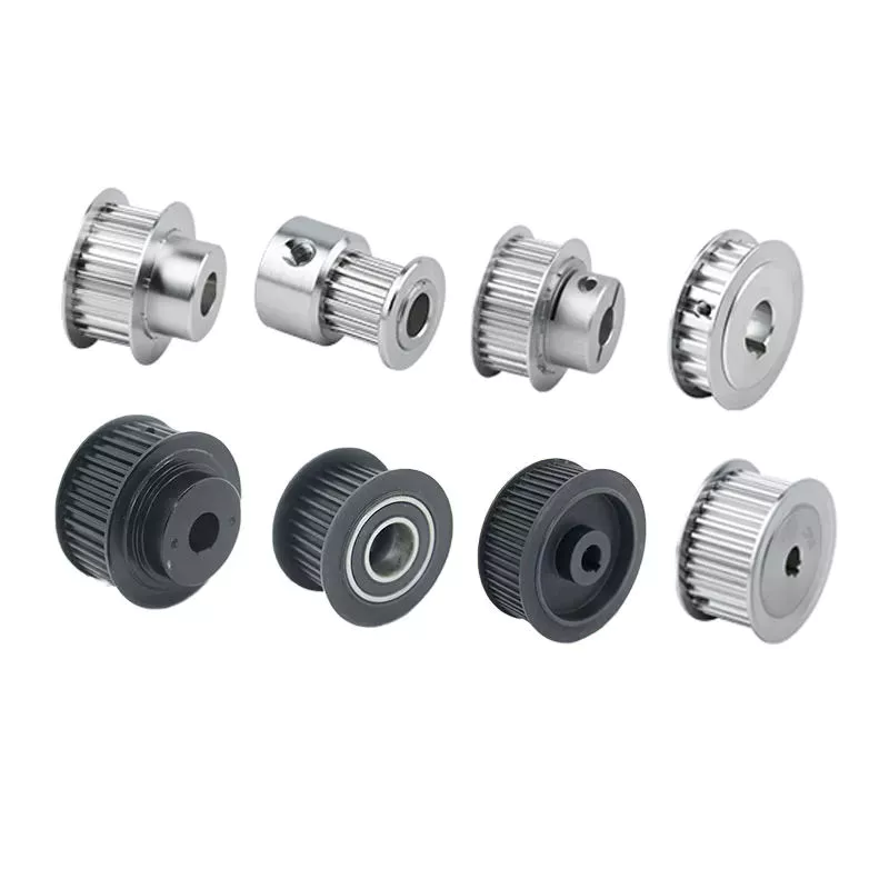
How to Assemble a Pulley System

A pulley is a wheel that rotates on a shaft or shaft to support the movement of a taut cable. Pulleys allow power to be transmitted from the shaft to the cable.
pulley

Simple pulley

The simplest theory of operation of a pulley system assumes that the rope and weight are weightless and that the rope and pulley are not stretched. Since the force on the pulley is the same, the force on the pulley shaft must also be zero. Therefore, the force exerted on the pulley shaft is also distributed evenly between the 2 wires passing through the pulley. The force distribution is shown in Figure 1.
The use of simple pulleys is as old as history. Before the Industrial Revolution, people relied on muscle strength to carry heavy loads. Pulleys, levers and ramps make this possible. Today, we can see pulleys in a variety of systems, from exercise equipment to garage doors, and even rock climbers use them to help them reach greater heights. As you can see, these simple machines have been around for centuries and are used in everyday life.
Another simple pulley system is the pulley system. In this system, there is a fixed pulley at the top and a movable pulley at the bottom. The 2 pulleys are connected by a rope. This combination reduces the amount of work required to lift the load. Additionally, the ropes used in this system are usually made of rope and woven through the individual wheels of the pulley drum.
A pulley is an ingenious device that distributes weight evenly and can be used to lift heavy objects. It is easy to build and can be easily modified for a wide range of activities. Even young children can make their own with very few materials. You can also use simple household items such as washing machines, thin textbooks and even chopsticks. It's very useful and can be a great addition to your child's science and engineering activities.
The simplest pulley system is movable. The axis of the movable pulley can move freely in space. The load is attached to 1 end of the pulley and the other end to the stationary object. By applying force on the other end of the rope, the load is lifted. The force at the other end of the rope is equal to the force at the free end of the pulley.
Another form of pulley is the compound pulley. Compound pulleys use 2 or more wheels to transmit force. Compound pulleys have 2 or more wheels and can lift heavier objects. Dim is POLE2.
pulley

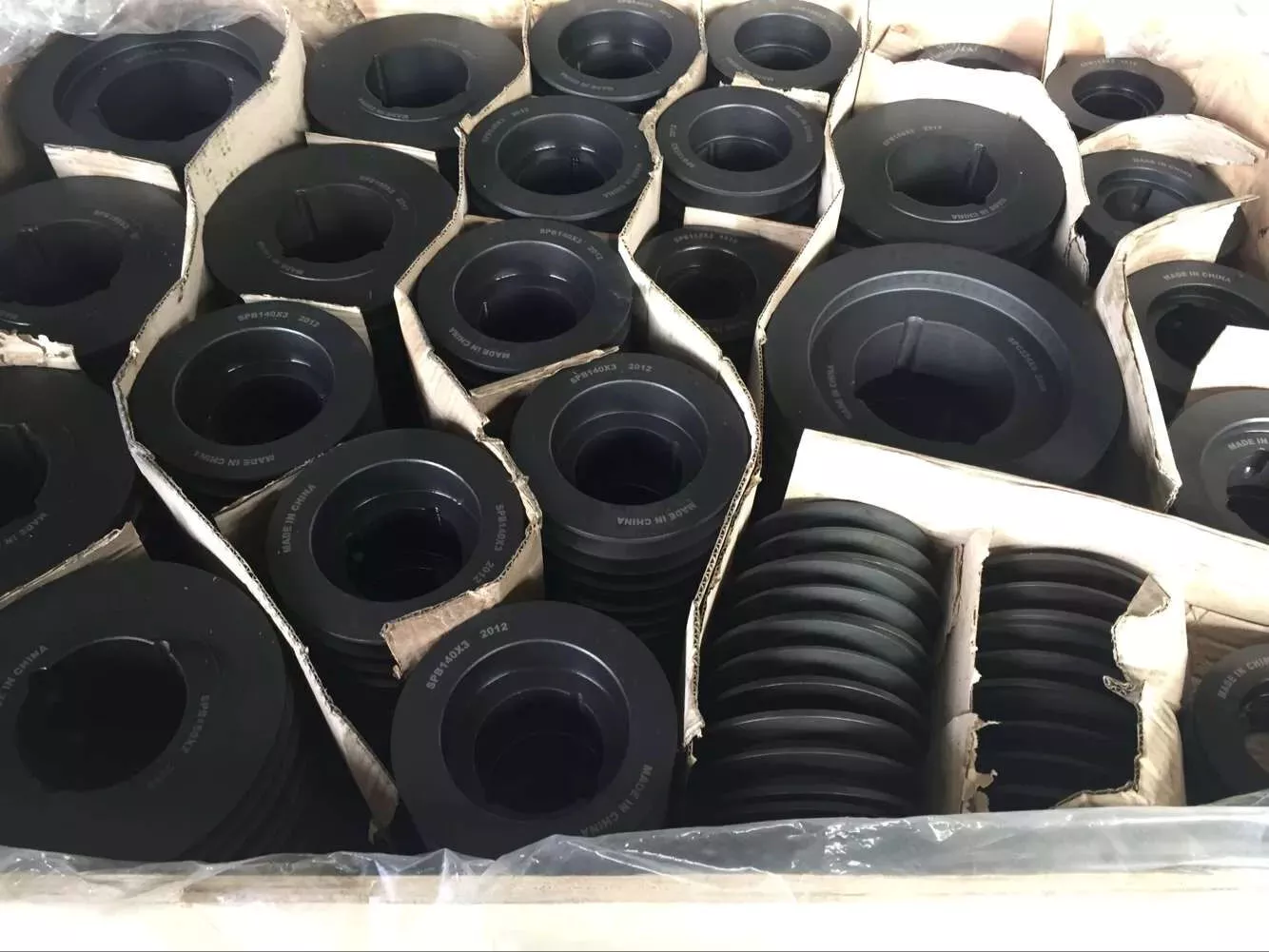
tapered pulley

It is important to clean and align the bolt holes before assembling the tapered pulley. The screws should be lubricated and the threads cleaned before installation. To install the pulley, insert it into the shaft keyway. The keyway should be aligned with the shaft hole to prevent foreign matter from entering the pulley. Then, alternately tighten the bolts until the pulley is tightened to the desired torque.
A tapered pulley is a basic structure. The pulley belt is arranged across 4 steps. Installed between the headstock casting and the main shaft, it is often used in the paper industry. It integrates with printing machinery and supports assembly lines. These pulleys are also available in metric range options, eliminating the need for ke-waying or re-drilling. They are easy to install, and users can even customize them to suit their needs.
CZPT Private Limited is a company that provides unique products for various industries. This large product is used for many different purposes. Also, it is manufactured for industrial use. The company's website provides detailed specifications for the product. If you need a tapered pulley, contact a company in your area today to purchase a quality product!
Tapered pulleys are vital to paper mill machinery. Its special design and construction enable it to transmit power from the engine source to the drive components. The advantages of this pulley include low maintenance costs and high mechanical strength. Cone wheel diameters range from 10 inches to 74 inches. These pulleys are commonly used in paper mills as they offer low maintenance, high mechanical strength and low wear.
A tapered sleeve connects the pulley to the shaft and forms an interference fit connector. The taper sleeve is fixed on the shaft with a key, and the corresponding inner hole is fixed on the shaft with a key. These features transmit torque and force to the pulley through friction. This allows the tapered pulley to move in a circular motion. The torque transfer characteristics of this pulley are most effective in high speed applications.
The sleeve is the most important part when assembling the tapered pulley. There is an 8-degree taper inside the cone, which is closely connected to the inner surface of the pulley. Taper sleeves and pulleys are interchangeable. However, tapered pulleys can be damaged after prolonged use.
pulley

pulley pulley system

A pulley pulley system is a great way to move heavy objects. These systems have been around for centuries, dating back to the ancient Greeks. This simple mechanism enables a person to lift heavy objects. These blocks are usually made of rope, and the number of turns varies for different types of rope. Some blocks have more cords than others, which creates friction and interferes with the easy movement of the lifting system.
When using a pulley pulley, the first thing to decide is which direction to pull. Unfavorable rigging means pulling in the opposite direction. In theory, this method is less efficient, but sometimes requires a certain amount of work space. The benefit is that you will increase the mechanical advantage of the pulley by pulling in the opposite direction. So the interception and tackle system will give you more of a mechanical advantage.
Pulley pulleys are an excellent choice for lifting heavy objects. The system is simple to install and users can easily lift objects without extensive training. Figure 3.40 shows a pulley in action. In this photo, the person on the left is pulling a rope and tying the end of the rope to a weight. When the rope is attached to the load, the rope will be pulled over the pulley and pulley.
The blocks on the blocks are attached to the ends of the rope. This creates unique lifting advantages compared to single-line systems. In Figure 3, the tension of each thread is equal to one-third of the unit weight. When the rope is pulled over the pulley, the force is divided equally between the 2 wires. The other pulley reverses the direction of the force, but that doesn't add any advantage.
Use pulleys to reduce traction and load. The weight of the load has not changed, but the length of the rope has increased. Using this method, lifting the load by pulling the rope 4 times reduces the force required to lift 1 foot. Likewise, if the pulley system had 4 pulleys instead of three, the length of the rope would be tripled.
The system can transmit loads in any direction. Rope length is determined by multiplying the distance from the fixed block to the load by the mechanical advantage. If the mechanical advantage is 3:1, then passing the rope through the pulley 3 times will produce the required traction distance. Also, the length of the rope will depend on the mechanical advantage, so if the load is 3 times the length of the rope, it will be more than 3 times the required length.

China wholesaler Hand Held Weeding Machine Grass Cutter Trimmer Tools Spare Parts Clutch Lawn Mower Metal Sintered Parts Clutch     with Hot sellingChina wholesaler Hand Held Weeding Machine Grass Cutter Trimmer Tools Spare Parts Clutch Lawn Mower Metal Sintered Parts Clutch     with Hot selling

China factory Hot Sale Grass Wrapping Machine Square Baler near me supplier

Product Description

Hot Sale Grass Wrapping Machine Square Baler
-
Square baler, square hay baler,square baler macine,square baler for sale

1.Square Baler Introduction
The tractor-type square bale baler produced by our company is mainly used for harvesting and bundling wheat stalks, rice stalks, cotton stalks, corn stalks, and various pasture grasses. It can effectively increase the speed and efficiency of straw harvesting, reduce harvesting costs, and alleviate the pressure on farmers to rush for crops in the "three summers" and "three autumns" seasons.

2.Square Baler Specification
Square baler-Professional manufacturer

Dimensions

4900×2870×1720mm

Machine weight:

1800kg

Pickup width:

2200mm

Supporting power:

≥30KW

Bale length:

30~132cm (adjustable)

Straw bale cross-section size

360×460mm

Power output shaft speed

540r/min

Bale density

120~180kg/m3

Piston rated reciprocating times

100 times/min

Piston stroke length

550mm

3.Square Baler Features

Multifunction
Higher efficiency than round baler
Bales length and density adjustable
Easy for operation
Good knotter & stable quality
The gearbox output is protected by shear bolt
Suitable for small farmland

4. Square Baler Highlights

Traction Type
The Square baler is equipped with a wheeled tractor of more than 60 Horsepower.The square baler is operated by 1 tractor and suitable for all kinds of natural grassland, planting grassland and farmland.
 

Square Baler Automatic Cutting
Wide type low flat Spring -tooth drum type scavenging device,with copying wheels on both sides,can reduce the loss of grass sliver leakage, reduce the lifting height of hay pickup.
 

Automatic Pickup System
The Square Baler with automatic pickup system,which can improve work efficiency, making square baler stable and be used safely.
 

Frame Work
Wear-resisitant metal steel plate, longer service life of the square balee machine.Suitable for any complex terrain,labor saving.


5. Square Baler Details

Square baler pickup device make baler high collecting efficiency, clean forage,good crushing effect,good dust removal effect.
Wear resisting tires:large-textured non-skid tires improve grip.
Precision process:stable performance, easy maintence and long service life.

6.Product Qualification
Guoan Baler has CE certification for each product, we will give each equipment with a CE certification card to ensure that our product quality and reliable.

7.Packing & Shipping

Number of units shipped in container
20FT Container can load 2sets Square baler
40FT Container can load 4sets Square baler
Iron frame with films cover.
balers, mini baler, square baler, baling machine.

8.After Sales Service

1) 12 month warrranty
2) Baler Parts Delivery in 3-5days during warranty period
3) Video of working provided
4) Commen problem soloved in time
5) 24 hours service,Online instant chat to reply in time.
6) Spare parts service
100% original spare parts guarantee quality;
accuracy and timeliness;
Professional parcel logistics delivery in 3-5 days.
 

9.Company Profile

HangZhou Guoan Engineering Machinery Co., Ltd. was established in 2006. It is a comprehensive scientific and technological enterprise integrating scientific research, production and sales. The company mainly produces round bale balers, square bale balers, drum mowers, flail mowers, reciprocating mowers, disc mowers, silage machines, film wrapping machines And other new energy sanitation cleaning equipment and various agricultural machinery parts. The company has more than 50 million fixed assets and 153 employees. The company is located on Xihu (West Lake) Dis.an Middle Road, HangZhou Economic Development Zone, the international kite capital, with a superior environment and convenient transportation.

10.FAQ
1) Waht is the size of the square baler?
1600 Net Weight.
2) Does baler pickup and bundling corn straw?
Yes, the square baler can pickup corn stalks.
3) Size of bales?
360*460mm.
4) Which certifications do you have?
CE, ISO 9001.
5) What size of tractor suitable for this baler?
If your tractor will lift 1600kg, it will operate our squared balers.
If your tractor has 60 to 100 PTO HP, then it will operate our compact hay balers.

11.Inquiry
If you have any questions, you can send an inquiry to us, and we will answer it in time. Any suggestion or idea you have is an important factor for our continuous progress. Appreciated to your letter.

Screw Shaft Types

A screw shaft is a cylindrical part that turns. Depending on its size, it is able to drive many different types of devices. The following information outlines the different types of screws, including their sizes, material, function, and applications. To help you select the right screw shaft, consider the following factors:
screwshaft

Size

A screw can come in a variety of shapes and sizes, ranging from a quarter to a quarter-inch in diameter. A screw is a cylindrical shaft with an inclined plane wrapped around it, and its main function is to fasten objects together by translating torque into a linear force. This article will discuss the dimensions of screws and how to determine the size of a screw. It is important to note that screw sizes can be large and small depending on the purpose.
The diameter of a screw is the diameter of its shaft, and it must match the inner diameter of its nuts and washers. Screws of a certain diameter are also called machine screws, and they can be larger or smaller. Screw diameters are measured on the shaft underneath the screw head. The American Society of Mechanical Engineers (ASME) standardized screw diameters in 3/50-inch to 16 (3/8-inch) inches, and more recently, sizes were added in U.S. fractions of an inch. While shaft and head diameters are standardized, screw length may vary from job to job.
In the case of the 2.3-mm screw group, the construct strength was not improved by the 1.2-mm group. The smaller screw size did not increase the strength of the construct. Further, ABS material did not improve the construct strength. Thus, the size of screw shaft is an important consideration in model design. And remember that the more complex your model is, the larger it will be. A screw of a given size will have a similar failure rate as a screw of a different diameter.
Although different screw sizes are widely used, the differences in screw size were not statistically significant. Although there are some limitations, screws of different sizes are generally sufficient for fixation of a metacarpal shaft fracture. However, further clinical studies are needed to compare screw sizes for fracture union rates. So, if you are unsure of what size of screw shaft you need for your case, make sure to check the metric chart and ensure you use the right one.
screwshaft

Material

The material of a screw shaft plays an important role in the overall performance of a screw. Axial and central forces act to apply torque to the screw, while external forces, such as friction, exert a bending moment. The torsional moments are reflected in the torque, and this causes the screw to rotate at a higher rate than necessary. To ensure the longevity of the screw, the material of the screw shaft should be able to handle the bending moment, while the diameter of the shaft should be small enough to avoid causing damage.
Screws are made from different metals, such as steel, brass, titanium, and bronze. Manufacturers often apply a top coating of chromium, brass, or zinc to improve corrosion resistance. Screws made of aluminum are not durable and are prone to rusting due to exposure to weather conditions. The majority of screw shafts are self-locking. They are suited for many applications, including threaded fasteners, C-clamps, and vises.
Screws that are fabricated with conical sections typically feature reduced open cross-sectional areas at the discharge point. This is a key design parameter of conical screw shafts. In fact, reductions of up to 72% are common across a variety of applications. If the screw is designed to have a hard-iron hanger bearing, it must be hardened. If the screw shaft is not hardened, it will require an additional lubricant.
Another consideration is the threads. Screw shafts are typically made of high-precision threads and ridges. These are manufactured on lathes and CNC machines. Different shapes require different materials. Materials for the screw shaft vary. There are many different sizes and shapes available, and each 1 has its own application. In addition to helical and conical screw shafts, different materials are also available. When choosing material, the best 1 depends on the application.
The life of the screw depends on its size, load, and design. In general, the material of the screw shaft, nut body, and balls and rollers determine its fatigue life. This affects the overall life of the screw. To determine whether a specific screw has a longer or shorter life, the manufacturer must consider these factors, as well as the application requirements. The material should be clean and free of imperfections. It should be smooth and free of cracks or flaking, which may result in premature failure.

Function

The function of a screw shaft is to facilitate the rotation of a screw. Screws have several thread forms, including single-start, double-start and multi-start. Each form has its own advantages and disadvantages. In this article we'll explore each of them in detail. The function of a screw shaft can vary based on its design, but the following are common types. Here are some examples of screw shaft types and their purposes.
The screw's torque enables it to lift objects. It can be used in conjunction with a bolt and nut to lift a load. Screws are also used to secure objects together. You can use them in screw presses, vises, and screw jacks. But their primary function is to hold objects together. Listed below are some of their main functions. When used to lift heavy loads, they can provide the required force to secure an object.
Screws can be classified into 2 types: square and round. Square threads are more efficient than round ones because they apply 0deg of angle to the nut. Square threads are also stronger than round threads and are often used in high-load applications. They're generally cheaper to manufacture and are more difficult to break. And unlike square threads, which have a 0deg thread angle, these threads can't be broken easily with a screwdriver.
A screw's head is made of a series of spiral-like structures that extend from a cylindrical part to a tip. This portion of the screw is called the shank and is made of the smallest area. The shank is the portion that applies more force to the object. As the shaft extends from the head, it becomes thinner and narrow, forming a pointed tip. The head is the most important part of the screw, so it needs to be strong to perform its function.
The diameter of the screw shaft is measured in millimeters. The M8 screw has a thread pitch of 1.25 mm. Generally, the size of the screw shaft is indicated by the major and minor diameter. These dimensions are appended with a multiplication sign (M8x1).
screwshaft

Applications

The design of screws, including their size and shape, determines their critical rotating speeds. These speeds depend on the threaded part of the screw, the helix angle, and the geometry of the contact surfaces. When applied to a screw, these limits are referred to as "permissible speed limits." These maximum speeds are meant for short periods of time and optimized running conditions. Continuous operation at these speeds can reduce the calculated life of a nut mechanism.
The main materials used to manufacture screws and screw shafts include steel, stainless steel, titanium, bronze, and brass. Screws may be coated for corrosion resistance, or they may be made of aluminium. Some materials can be threaded, including Teflon and nylon. Screw threads can even be molded into glass or porcelain. For the most part, steel and stainless steel are the most common materials for screw shafts. Depending on the purpose, a screw will be made of a material that is suitable for the application.
In addition to being used in fasteners, screw shafts are used in micrometers, drillers, conveyor belts, and helicopter blades. There are numerous applications of screw shafts, from weighing scales to measuring lengths. If you're in the market for a screw, make sure to check out these applications. You'll be happy you did! They can help you get the job done faster. So, don't delay your next project.
If you're interested in learning about screw sizing, then it's important to know the axial and moment loads that your screws will experience. By following the laws of mechanics and knowing the load you can calculate the nominal life of your screw. You can also consider the effect of misalignment, uneven loading, and shocks on your screw. These will all affect the life of your screw. Then, you can select the right screw.

China factory Hot Sale Grass Wrapping Machine Square Baler     near me supplier China factory Hot Sale Grass Wrapping Machine Square Baler     near me supplier

China Good quality CE Approved Efgch Agricultural Machinery Grass Cutting Machine Tractor Light Grass Side Lawn Flail Lawn Finishing Mower with Side Shift Hydraulic Linkage near me manufacturer

Product Description

Product Description

Efgc&Efgch Series Flail Mower

PRODUCT DETAILS:
1.Transmission: By sturdy toothed belts.(VB Belt)
2.Graphite gearbox is made of casting iron
3.The suspension plate shape is made by laser cutting,molding location
4.With adjustable rear roller, the mowing height can be adjusted easily
5.Side protection plates are added CZPT the rear deflection
6.Y shape blades, hammer and straight blades for grass. (Optional for customers.)
7.The blades are under hot dealing and special testing
8.With front protection, to avoid splashing
9. Use powder painting
10.Labels are:water proof, damp proof, CZPT proof, anti-ultraviolet radiation

Guarantee & Warranty: 1.Warranty time:14months,longer than any other Chinese suppliers. 2.With CE CERTIFICATES. 3.All of your ordered machines will be tested to ensure the quality before shipment. 4.We will provide you with the test reports together with the container or sample packages. 5.Even the packages,all of them are guaranteed for customs check or inspections.

CE Approved Efgch Agricultural Machinery Grass Cutting Machine Tractor Light Grass Side Lawn Flail Lawn Finishing Mower with Side Shift Hydraulic Linkage

Main Products

Why Choose Us

Company Profile

HangZhou BETTER. AGRO Industry (B.T.A), as 1 of the leading manufacturers in the production of agricultural equipments, is located in TiHangZhou District, HangZhou, ZheJiang , China, with good location, convenient transportation and complement resources.

B.T.A's motto is "tending to the details others can 't ", and it is committed to creating the top brand in the high-end agricultural machinery. In line with the philosophy of "taking the initiative to participate in market competition", B.T.A spares no effort to design and develop the most professional and the most sophisticated new types of agricultural machinery products.

B.T.A has professional laser cutting machines, fully automatic CNC bending machines, standard welding jigs and automatic spraying production line and other advanced production equipment, as well as excellent technology research and development team. It strictly follows European & American Design and Use Standard and adopts an advanced management system and strict quality control. It not only gives strict product performance assessment according to the field test specification and passed the CE certification, but also constantly improves and upgrades products after user feedback. B.T.A is well known with its superior design, rich varieties and reliable quality, it is especially recognized in the United States, Germany, Netherlands, Belgium, Australia and other countries.

B.T.A is mainly engaged in the research and development, manufacturing and sales of various types of agricultural and garden machinery. Our main products are divided into our categories: farm machinery, garden machinery, forestry machinery and road machinery. Some of our well known products include 3 point linkage rotary tiller, finishing mower, flail mower, verge flail mower, rotary slasher, wood chipper, trailer, spare parts and Japanese tractor accessories, which are exported to over 20 countries.

In the future, B.T.A will further optimize the structure of existing products according to the requirements and characteristics of farmers, satisfy the needs of the international market and establish the perfect after-sales service system.

Certifications

FAQ

Q1. What are your terms of packing?

A: Generally, we pack our goods in bulks or wooden box, suitable for shipping container.


Q2. What is your terms of payment?

A: T/T 30% as deposit, and 70% before delivery. We'll show you the photos of the products and packages before you pay the balance.


Q3. What are your terms of delivery?

A: EXW, FOB, CFR, CIF.


Q4. How about your delivery time?

A: Generally, it will take 10 to 15 days after receiving your advance payment. The specific delivery time depends 

on the items and the quantity of your order. 


Q5. Can you produce according to the samples?

A: Yes, we can produce by your samples or technical drawings.


Q6. What is your sample policy?

A: We can supply the sample if we have ready parts in stock.


Q7. Do you test all your goods before delivery?

A: Yes, we have 100% test before delivery.


Q8: How do you make our business long-term and good relationship?

A1:We keep excellent quality, thoughtful after-sales service and competitive price to ensure our customers' benefit;

A2:We respect every customer as our friend and we sincerely do business and make friends with them, no matter where they come from

The Difference Between Planetary Gears and Spur Gears

A spur gear is a type of mechanical drive that turns an external shaft. The angular velocity is proportional to the rpm and can be easily calculated from the gear ratio. However, to properly calculate angular velocity, it is necessary to know the number of teeth. Fortunately, there are several different types of spur gears. Here's an overview of their main features. This article also discusses planetary gears, which are smaller, more robust, and more power-dense.
Planetary gears are a type of spur gear

One of the most significant differences between planetary gears and spurgears is the way that the 2 share the load. Planetary gears are much more efficient than spurgears, enabling high torque transfer in a small space. This is because planetary gears have multiple teeth instead of just one. They are also suitable for intermittent and constant operation. This article will cover some of the main benefits of planetary gears and their differences from spurgears.
While spur gears are more simple than planetary gears, they do have some key differences. In addition to being more basic, they do not require any special cuts or angles. Moreover, the tooth shape of spur gears is much more complex than those of planetary gears. The design determines where the teeth make contact and how much power is available. However, a planetary gear system will be more efficient if the teeth are lubricated internally.
In a planetary gear, there are 3 shafts: a sun gear, a planet carrier, and an external ring gear. A planetary gear is designed to allow the motion of 1 shaft to be arrested, while the other 2 work simultaneously. In addition to two-shaft operation, planetary gears can also be used in three-shaft operations, which are called temporary three-shaft operations. Temporary three-shaft operations are possible through frictional coupling.
Among the many benefits of planetary gears is their adaptability. As the load is shared between several planet gears, it is easier to switch gear ratios, so you do not need to purchase a new gearbox for every new application. Another major benefit of planetary gears is that they are highly resistant to high shock loads and demanding conditions. This means that they are used in many industries.
Gear

They are more robust

An epicyclic gear train is a type of transmission that uses concentric axes for input and output. This type of transmission is often used in vehicles with automatic transmissions, such as a Lamborghini Gallardo. It is also used in hybrid cars. These types of transmissions are also more robust than conventional planetary gears. However, they require more assembly time than a conventional parallel shaft gear.
An epicyclic gearing system has 3 basic components: an input, an output, and a carrier. The number of teeth in each gear determines the ratio of input rotation to output rotation. In some cases, an epicyclic gear system can be made with 2 planets. A third planet, known as the carrier, meshes with the second planet and the sun gear to provide reversibility. A ring gear is made of several components, and a planetary gear may contain many gears.
An epicyclic gear train can be built so that the planet gear rolls inside the pitch circle of an outer fixed gear ring, or "annular gear." In such a case, the curve of the planet's pitch circle is called a hypocycloid. When epicycle gear trains are used in combination with a sun gear, the planetary gear train is made up of both types. The sun gear is usually fixed, while the ring gear is driven.
Planetary gearing, also known as epicyclic gear, is more durable than other types of transmissions. Because planets are evenly distributed around the sun, they have an even distribution of gears. Because they are more robust, they can handle higher torques, reductions, and overhung loads. They are also more energy-dense and robust. In addition, planetary gearing is often able to be converted to various ratios.
Gear

They are more power dense

The planet gear and ring gear of a compound planetary transmission are epicyclic stages. One part of the planet gear meshes with the sun gear, while the other part of the gear drives the ring gear. Coast tooth flanks are used only when the gear drive works in reversed load direction. Asymmetry factor optimization equalizes the contact stress safety factors of a planetary gear. The permissible contact stress, sHPd, and the maximum operating contact stress (sHPc) are equalized by asymmetry factor optimization.
In addition, epicyclic gears are generally smaller and require fewer space than helical ones. They are commonly used as differential gears in speed frames and in looms, where they act as a Roper positive let off. They differ in the amount of overdrive and undergearing ratio they possess. The overdrive ratio varies from 15 percent to 40 percent. In contrast, the undergearing ratio ranges from 0.87:1 to 69%.
The TV7-117S turboprop engine gearbox is the first known application of epicyclic gears with asymmetric teeth. This gearbox was developed by the CZPT Corporation for the Ilyushin Il-114 turboprop plane. The TV7-117S's gearbox arrangement consists of a first planetary-differential stage with 3 planet gears and a second solar-type coaxial stage with 5 planet gears. This arrangement gives epicyclic gears the highest power density.
Planetary gearing is more robust and power-dense than other types of gearing. They can withstand higher torques, reductions, and overhung loads. Their unique self-aligning properties also make them highly versatile in rugged applications. It is also more compact and lightweight. In addition to this, epicyclic gears are easier to manufacture than planetary gears. And as a bonus, they are much less expensive.

They are smaller

Epicyclic gears are small mechanical devices that have a central "sun" gear and 1 or more outer intermediate gears. These gears are held in a carrier or ring gear and have multiple mesh considerations. The system can be sized and speeded by dividing the required ratio by the number of teeth per gear. This process is known as gearing and is used in many types of gearing systems.
Planetary gears are also known as epicyclic gearing. They have input and output shafts that are coaxially arranged. Each planet contains a gear wheel that meshes with the sun gear. These gears are small and easy to manufacture. Another advantage of epicyclic gears is their robust design. They are easily converted into different ratios. They are also highly efficient. In addition, planetary gear trains can be designed to operate in multiple directions.
Another advantage of epicyclic gearing is their reduced size. They are often used for small-scale applications. The lower cost is associated with the reduced manufacturing time. Epicyclic gears should not be made on N/C milling machines. The epicyclic carrier should be cast and tooled on a single-purpose machine, which has several cutters cutting through material. The epicyclic carrier is smaller than the epicyclic gear.
Epicyclic gearing systems consist of 3 basic components: an input, an output, and a stationary component. The number of teeth in each gear determines the ratio of input rotation to output rotation. Typically, these gear sets are made of 3 separate pieces: the input gear, the output gear, and the stationary component. Depending on the size of the input and output gear, the ratio between the 2 components is greater than half.
Gear

They have higher gear ratios

The differences between epicyclic gears and regular, non-epicyclic gears are significant for many different applications. In particular, epicyclic gears have higher gear ratios. The reason behind this is that epicyclic gears require multiple mesh considerations. The epicyclic gears are designed to calculate the number of load application cycles per unit time. The sun gear, for example, is +1300 RPM. The planet gear, on the other hand, is +1700 RPM. The ring gear is also +1400 RPM, as determined by the number of teeth in each gear.
Torque is the twisting force of a gear, and the bigger the gear, the higher the torque. However, since the torque is also proportional to the size of the gear, bigger radii result in lower torque. In addition, smaller radii do not move cars faster, so the higher gear ratios do not move at highway speeds. The tradeoff between speed and torque is the gear ratio.
Planetary gears use multiple mechanisms to increase the gear ratio. Those using epicyclic gears have multiple gear sets, including a sun, a ring, and 2 planets. Moreover, the planetary gears are based on helical, bevel, and spur gears. In general, the higher gear ratios of epicyclic gears are superior to those of planetary gears.
Another example of planetary gears is the compound planet. This gear design has 2 different-sized gears on either end of a common casting. The large end engages the sun while the smaller end engages the annulus. The compound planets are sometimes necessary to achieve smaller steps in gear ratio. As with any gear, the correct alignment of planet pins is essential for proper operation. If the planets are not aligned properly, it may result in rough running or premature breakdown.

China Good quality CE Approved Efgch Agricultural Machinery Grass Cutting Machine Tractor Light Grass Side Lawn Flail Lawn Finishing Mower with Side Shift Hydraulic Linkage     near me manufacturer China Good quality CE Approved Efgch Agricultural Machinery Grass Cutting Machine Tractor Light Grass Side Lawn Flail Lawn Finishing Mower with Side Shift Hydraulic Linkage     near me manufacturer

China Best Sales Grass Cutting Machine Backpack Mini Weeder Machine for Sale near me shop

Product Description

Product Description

Portable Multifunctional Grass Cutter Machine 2 Stroke Gasoline Engine Weeder
 

Model  KF-12,KF-14
Engine  Gasoline engine 
Stock  2 stroke, 4 stroke
Cylinder Single cylinder 
Power  1.25KW,0.75KW 
Displacement  40CC,31CC
Control lever length  1500mm
Weight 23KG
Head kinds  6 kinds to choose 


Detailed Photos

Packaging & Shipping

Company Profile

HangZhou Rafiki Tools Co.,Ltd & HangZhou CZPT Machinery Co.,Ltd.

   We are a professional company producing agriculture machinery and spare parts. Our company highly combines developing, manufacturing, selling and service. We located in Tantang Industrial Park, Xihu (West Lake) Dis. County, which is the "South Gate" of ZheJiang province, well known as "backyard garden of Hong Kong & Macao". Tantang Industrial Park is the hometown of Chinese casting nonferrous material, which enjoys beautiful scenery, convenient transportation, high machinery design level, strong processing ability and rich scientific research atmosphere.
    Our company always insists manufacturing high quality products, developing technology, offering best service. We sincerely welcome customers and friends from home and abroad and we will try best to make you all feel satisfied.


Our Advantages

1. Mini Manual Brush cutter / Hot Sale Rotary Weeder is designed especially for rice field and garden weeding 

2.The professional rotary Brush cutter designcould loosen soil avoid soil hardening.

3.This Brush cutter machine have 6 kinds heads with 6 functions.

4.It is the essential garden and farm tool for cultivating rice ,Which has the advantages of small and light machine body,easy to move ,economical and practical for farming

Worm Gear Motors

Worm gear motors are often preferred for quieter operation because of the smooth sliding motion of the worm shaft. Unlike gear motors with teeth, which may click as the worm turns, worm gear motors can be installed in a quiet area. In this article, we will talk about the CZPT whirling process and the various types of worms available. We'll also discuss the benefits of worm gear motors and worm wheel.
worm shaft

worm gear

In the case of a worm gear, the axial pitch of the ring pinion of the corresponding revolving worm is equal to the circular pitch of the mating revolving pinion of the worm gear. A worm with 1 start is known as a worm with a lead. This leads to a smaller worm wheel. Worms can work in tight spaces because of their small profile.
Generally, a worm gear has high efficiency, but there are a few disadvantages. Worm gears are not recommended for high-heat applications because of their high level of rubbing. A full-fluid lubricant film and the low wear level of the gear reduce friction and wear. Worm gears also have a lower wear rate than a standard gear. The worm shaft and worm gear is also more efficient than a standard gear.
The worm gear shaft is cradled within a self-aligning bearing block that is attached to the gearbox casing. The eccentric housing has radial bearings on both ends, enabling it to engage with the worm gear wheel. The drive is transferred to the worm gear shaft through bevel gears 13A, 1 fixed at the ends of the worm gear shaft and the other in the center of the cross-shaft.

worm wheel

In a worm gearbox, the pinion or worm gear is centered between a geared cylinder and a worm shaft. The worm gear shaft is supported at either end by a radial thrust bearing. A gearbox's cross-shaft is fixed to a suitable drive means and pivotally attached to the worm wheel. The input drive is transferred to the worm gear shaft 10 through bevel gears 13A, 1 of which is fixed to the end of the worm gear shaft and the other at the centre of the cross-shaft.
Worms and worm wheels are available in several materials. The worm wheel is made of bronze alloy, aluminum, or steel. Aluminum bronze worm wheels are a good choice for high-speed applications. Cast iron worm wheels are cheap and suitable for light loads. MC nylon worm wheels are highly wear-resistant and machinable. Aluminum bronze worm wheels are available and are good for applications with severe wear conditions.
When designing a worm wheel, it is vital to determine the correct lubricant for the worm shaft and a corresponding worm wheel. A suitable lubricant should have a kinematic viscosity of 300 mm2/s and be used for worm wheel sleeve bearings. The worm wheel and worm shaft should be properly lubricated to ensure their longevity.

Multi-start worms

A multi-start worm gear screw jack combines the benefits of multiple starts with linear output speeds. The multi-start worm shaft reduces the effects of single start worms and large ratio gears. Both types of worm gears have a reversible worm that can be reversed or stopped by hand, depending on the application. The worm gear's self-locking ability depends on the lead angle, pressure angle, and friction coefficient.
A single-start worm has a single thread running the length of its shaft. The worm advances 1 tooth per revolution. A multi-start worm has multiple threads in each of its threads. The gear reduction on a multi-start worm is equal to the number of teeth on the gear minus the number of starts on the worm shaft. In general, a multi-start worm has 2 or 3 threads.
Worm gears can be quieter than other types of gears because the worm shaft glides rather than clicking. This makes them an excellent choice for applications where noise is a concern. Worm gears can be made of softer material, making them more noise-tolerant. In addition, they can withstand shock loads. Compared to gears with toothed teeth, worm gears have a lower noise and vibration rate.
worm shaft

CZPT whirling process

The CZPT whirling process for worm shafts raises the bar for precision gear machining in small to medium production volumes. The CZPT whirling process reduces thread rolling, increases worm quality, and offers reduced cycle times. The CZPT LWN-90 whirling machine features a steel bed, programmable force tailstock, and five-axis interpolation for increased accuracy and quality.
Its 4,000-rpm, 5-kW whirling spindle produces worms and various types of screws. Its outer diameters are up to 2.5 inches, while its length is up to 20 inches. Its dry-cutting process uses a vortex tube to deliver chilled compressed air to the cutting point. Oil is also added to the mixture. The worm shafts produced are free of undercuts, reducing the amount of machining required.
Induction hardening is a process that takes advantage of the whirling process. The induction hardening process utilizes alternating current (AC) to cause eddy currents in metallic objects. The higher the frequency, the higher the surface temperature. The electrical frequency is monitored through sensors to prevent overheating. Induction heating is programmable so that only certain parts of the worm shaft will harden.

Common tangent at an arbitrary point on both surfaces of the worm wheel

A worm gear consists of 2 helical segments with a helix angle equal to 90 degrees. This shape allows the worm to rotate with more than 1 tooth per rotation. A worm's helix angle is usually close to 90 degrees and the body length is fairly long in the axial direction. A worm gear with a lead angle g has similar properties as a screw gear with a helix angle of 90 degrees.
The axial cross section of a worm gear is not conventionally trapezoidal. Instead, the linear part of the oblique side is replaced by cycloid curves. These curves have a common tangent near the pitch line. The worm wheel is then formed by gear cutting, resulting in a gear with 2 meshing surfaces. This worm gear can rotate at high speeds and still operate quietly.
A worm wheel with a cycloid pitch is a more efficient worm gear. It reduces friction between the worm and the gear, resulting in greater durability, improved operating efficiency, and reduced noise. This pitch line also helps the worm wheel engage more evenly and smoothly. Moreover, it prevents interference with their appearance. It also makes worm wheel and gear engagement smoother.
worm shaft

Calculation of worm shaft deflection

There are several methods for calculating worm shaft deflection, and each method has its own set of disadvantages. These commonly used methods provide good approximations but are inadequate for determining the actual worm shaft deflection. For example, these methods do not account for the geometric modifications to the worm, such as its helical winding of teeth. Furthermore, they overestimate the stiffening effect of the gearing. Hence, efficient thin worm shaft designs require other approaches.
Fortunately, several methods exist to determine the maximum worm shaft deflection. These methods use the finite element method, and include boundary conditions and parameter calculations. Here, we look at a couple of methods. The first method, DIN 3996, calculates the maximum worm shaft deflection based on the test results, while the second one, AGMA 6022, uses the root diameter of the worm as the equivalent bending diameter.
The second method focuses on the basic parameters of worm gearing. We'll take a closer look at each. We'll examine worm gearing teeth and the geometric factors that influence them. Commonly, the range of worm gearing teeth is 1 to four, but it can be as large as twelve. Choosing the teeth should depend on optimization requirements, including efficiency and weight. For example, if a worm gearing needs to be smaller than the previous model, then a small number of teeth will suffice.

China Best Sales Grass Cutting Machine Backpack Mini Weeder Machine for Sale     near me shop China Best Sales Grass Cutting Machine Backpack Mini Weeder Machine for Sale     near me shop