Tag Archives: machine shaft

China manufacturer Mining Parts Pinion Shaft for Large Machine Transmission Parts with high quality

Product Description

Mining Parts Forging Gear Shaft

Product Description

CIC is a more than 30 - year manufacturer and reputed supplier of forged shaft used in various machinery equipment in the fields of mining, metallurgical, chemical industry, construction, and so on. CIC possesses professional design team, advanced equipment and detecting method, strict quality control system to meet all your customized requirements of forged shaft. High quality, excellent performances and competitive price will make you rely on us and choose us.
 
CIC has manufactured many kinds of forged shafts, including forged roller, forged support roller shafts, forged thrust roller shafts, forged pinion shaft with gears both mounted to the shaft and as a part of the shaft, and other more kinds of forged shafts.
 
Bring us your challenges, and we will deliver solutions.
 
Features:
1. Material: stainless steel, carbon steel, alloy steel and as your requests
2. Standard: Standard: ANSI, API, ASTM, BSI, DIN, GB, ISO, JIS and more standards.
3. Mechanical Properties: customized requirements are accepted.
4. Hardness: customized requirements are accepted.
5. Surface treatment: rust preventive oil and according to your requirements.
6. Application: mainly used in various machinery equipment in the fields of mining, metallurgical, chemical industry, construction, and so on
7. QA and DOC: chemical composition report, mechanical properties report, UT report, PT report, heat treatment report, dimensions check report, hardness report and more
We can offer third party inspection.
8. Process: raw material purchasing - casting- rough machining - heat treatment - semi machining - finish machining - shrinkage fitting - painting and packing
Various process conditions are available.
9. Certificates: ISO 9001:2008
10. Products ability: Max length: 20m, Max OD: 2m
11. Heat treatment: quenching and tempering, normalizing and tempering.
12. QC: fabrication schedule, fabrication process chart, inspection and test plan
13. Packing: coated with rust preventive oil, seaworthy packing
 
 
Advantages:
1. More than 30 years experience
2. ISO9001:2008 Standard certified
3. Custom-made design
4. All seamless forged
5. Strict quality control 
6. Prompt delivery

Main Manufacturing Machines:

2×8m Numerical Controlled Horizontal Lathe

6×20m heavy Horizontal Lathe

200 Numerical Controlled Boring& Milling Machine


How to use the pulley system

Using a pulley system is a great way to move things around your home, but how do you use a pulley system? Let's look at the basic equations that describe a pulley system, the types of pulleys, and some safety considerations when using pulleys. Here are some examples. Don't worry, you'll find all the information you need in 1 place!
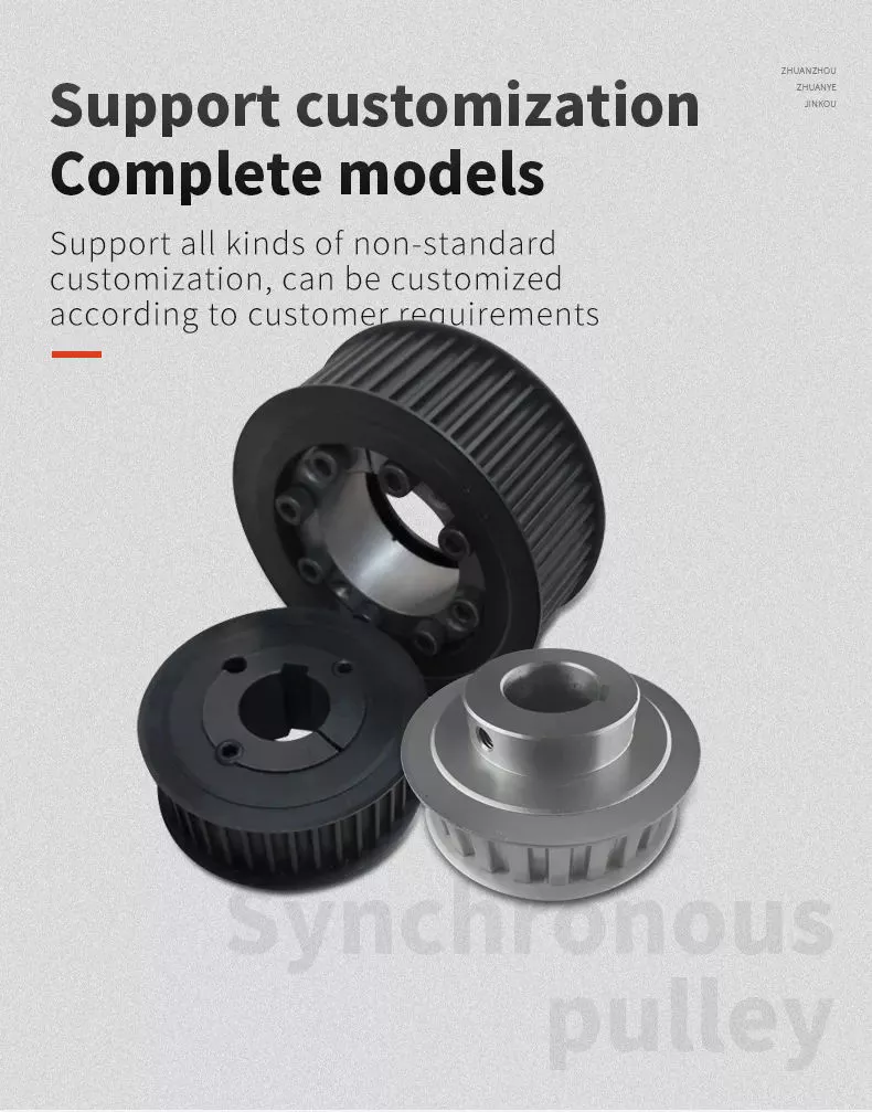
pulley

Basic equations of pulley systems

The pulley system consists of pulleys and chords. When the weight of the load is pulled through the rope, it slides through the groove and ends up on the other side. When the weight moves, the applied force must travel nx distance. The distance is in meters. If there are 4 pulleys, the distance the rope will travel will be 2x24. If there are n pulleys, the distance traveled by the weight will be 2n - 1.
The mechanical advantage of the pulley system increases with distance. The greater the distance over which the force is applied, the greater the leverage of the system. For example, if a set of pulleys is used to lift the load, 1 should be attached to the load and the other to the stand. The load itself does not move. Therefore, the distance between the blocks must be shortened, and the length of the line circulating between the pulleys must be shortened.
Another way to think about the acceleration of a pulley system is to think of ropes and ropes as massless and frictionless. Assuming the rope and pulley are massless, they should have the same magnitude and direction of motion. However, in this case the quality of the string is a variable that is not overdone. Therefore, the tension vector on the block is labeled with the same variable name as the pulley.
The calculation of the pulley system is relatively simple. Five mechanical advantages of the pulley system can be found. This is because the number of ropes supporting the load is equal to the force exerted on the ropes. When the ropes all move in the same direction, they have 2 mechanical advantages. Alternatively, you can use a combination of movable and fixed pulleys to reduce the force.
When calculating forces in a pulley system, you can use Newton's laws of motion. Newton's second law deals with acceleration and force. The fourth law tells us that tension and gravity are in equilibrium. This is useful if you need to lift heavy objects. The laws of motion help with calculations and can help you better understand pulley systems.
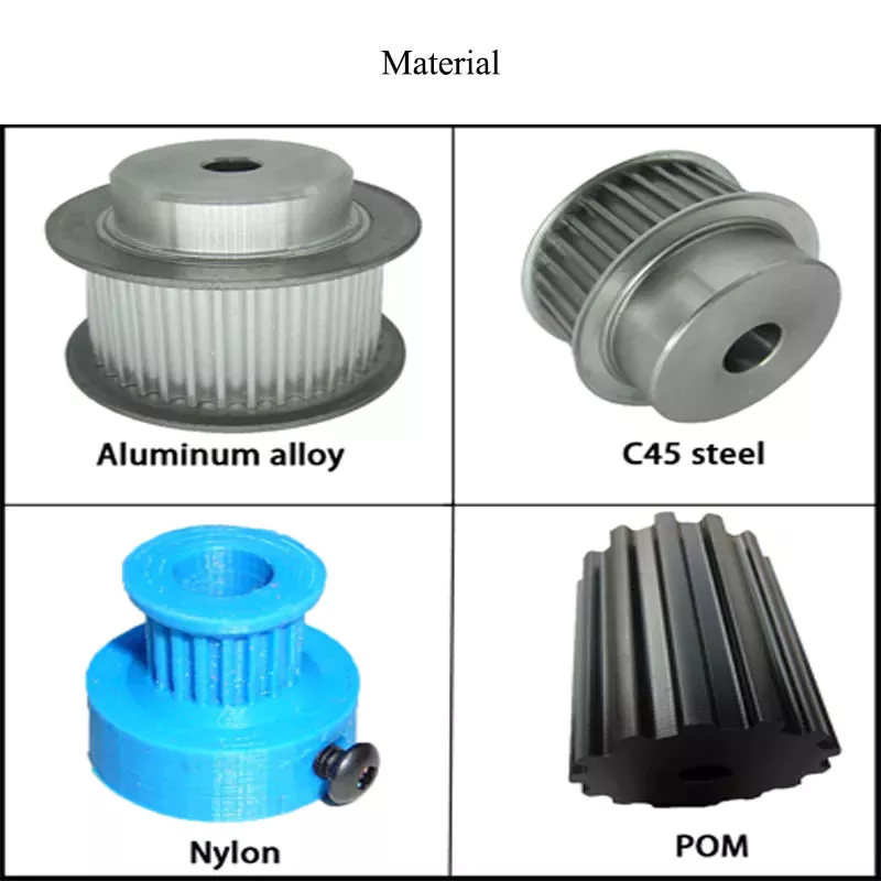
pulley

Types of pulleys

Different types of pulleys are commonly used for various purposes, including lifting. Some pulleys are flexible, which means they can move freely around a central axis and can change the direction of force. Some are fixed, such as hinges, and are usually used for heavier loads. Others are movable, such as coiled ropes. Whatever the purpose, pulleys are very useful in raising and lowering objects.
Pulleys are common in many different applications, from elevators and cargo lift systems to lights and curtains. They are also used in sewing machine motors and sliding doors. Garage and patio doors are often equipped with pulleys. Rock climbers use a pulley system to climb rocks safely. These pulley systems have different types of pinions that allow them to balance weight and force direction.
The most common type of pulley is the pulley pulley system. The pulley system utilizes mechanical advantages to lift weight. Archimedes is thought to have discovered the pulley around 250 BC. in ancient Sicily. Mesopotamians also used pulleys, they used ropes to lift water and windmills. Pulley systems can even be found at Stonehenge.
Another type of pulley is called a compound pulley. It consists of a set of parallel pulleys that increase the force required to move large objects. This type is most commonly used in rock climbing and sailing, while composite pulleys can also be found in theater curtains. If you're wondering the difference between these 2 types of pulleys, here's a quick overview:

Mechanical Advantages of Pulley Systems

Pulley systems offer significant mechanical advantages. The ability of the system to reduce the effort required to lift weights increases with the number of rope loops. This advantage is proportional to the number of loops in the system. If the rope had only 1 loop, then a single weight would require the same amount of force to pull. But by adding extra cycles, the force required will be reduced.
The pulley system has the advantage of changing the direction of the force. This makes it easier to move heavy objects. They come in both fixed and mobile. Pulleys are used in many engineering applications because they can be combined with other mechanisms. If you want to know what a pulley can do, read on! Here are some examples. Therefore, you will understand how they are used in engineering.
Single-acting pulleys do not change direction, but compound pulleys do. Their mechanical advantage is six. The compound pulley system consists of a movable pulley and a fixed pulley. The mechanical advantage of the pulley system increases as the number of movable wheels decreases. So if you have 2 wheels, you need twice as much force to lift the same weight because you need a movable pulley.
The mechanical advantage of a pulley system can be maximized by adding more pulleys or rope lengths. For example, if you have a single pulley system, the mechanical advantage is 1 of the smallest. By using 2 or 3 pulleys, up to 5 times the mechanical advantage can be achieved. You can also gain up to 10 times the mechanical advantage by using multiple pulley systems.
The use of a single movable pulley system also adds to the mechanical advantage of the pulley system. In this case, you don't have to change the direction of the force to lift the weight. In contrast, a movable pulley system requires you to move the rope farther to generate the same force. Using a compound pulley system allows you to lift heavy loads with ease.
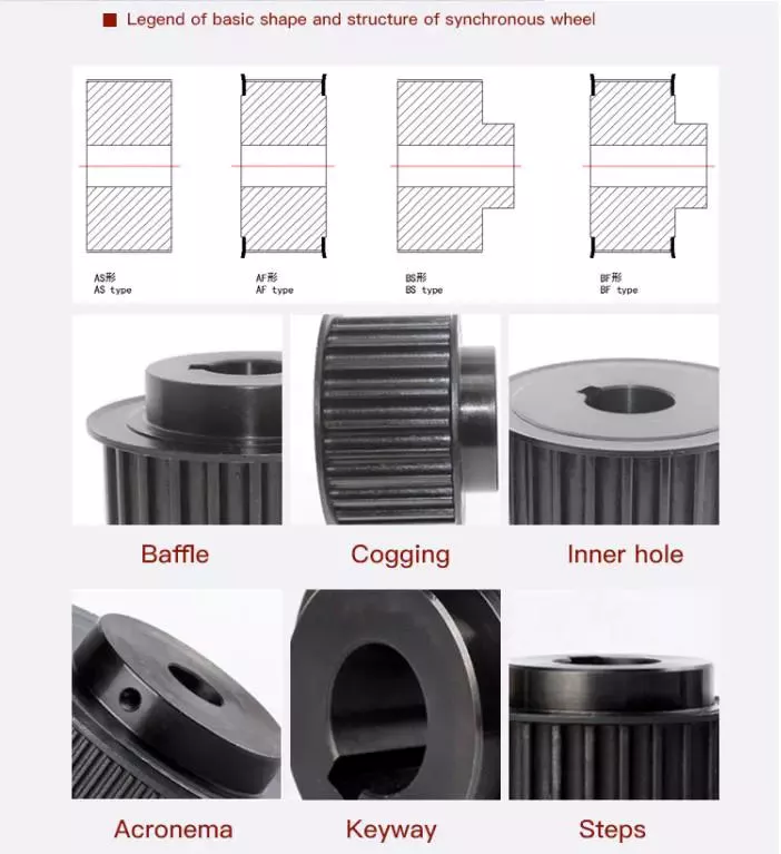
pulley

Safety Issues When Using Pulley Systems

Pulleys have an incredibly unique structure, consisting of a disc with a groove in the middle and a shaft running through it. A rope or cord is attached to 1 end of a pulley that turns when force is applied. The other end of the rope is attached to the load. This mechanical advantage means that it is much easier to pull an object using the pulley system than to lift the same object by hand.
Although pulley systems are a common part of many manufacturing processes, some employers do not train their workers to use them properly or install protection to prevent injury. It is important to wear proper PPE and follow standard laboratory safety practices during pulley system activities. Make sure any support structures are strong enough to handle the weight and weight of the rope or rope. If you do fall, be sure to contact your employer immediately.

China manufacturer Mining Parts Pinion Shaft for Large Machine Transmission Parts     with high qualityChina manufacturer Mining Parts Pinion Shaft for Large Machine Transmission Parts     with high quality

China factory Aly Machine YDW-200A Type II drive shaft three-section joint school drive shaft balancing machine with Best Sales

Product: 124 Spider (348_)
Calendar year: 2016-
Sort: Motor Analyzer
Voltage: NO
Car Fitment: Abarth
Power: NO
Relevant Designs: ALL
Mix: NO
Product Number: A
Guarantee: 12 Months
Top quality: Substantial-Quality
Packaging Particulars: paper box
Port: HangZhou

Aly Equipment YDW-200A Sort II travel shaft three-part joint college generate shaft balancing device

Merchandise Information

one. Introduction of 3-axis joint calibration travel shaft balancing machine
The a few-axis joint calibration drive shaft balancing machine is a unique balancing equipment, which is an excellent equipment for stability calibration of auto push shafts. It only wants to change the fixture for putting in the workpiece to execute dynamic stability correction of a variety of drive shafts. The equipment can not only carry out joint calibration of 3 transmission shafts, but also can perform solitary-axis calibration, and can also complete joint calibration of 2 transmission shafts the swing body adopts a comfortable assist composition, which is suited for measuring the unbalance of the transmission shaft at a higher speed, and the measurement result of the equipment is better. great.

2. Measurement program
1) ZheJiang industrial manage computer, 19-inch Lcd exhibit (touch display can be geared up in accordance to buyer requirements), Home windows working system
two) Outfitted with the special software program for push shaft equilibrium independently created by our organization. The software program can decide on 3 drive shaft calibration methods: solitary segment, 2 sections and 3 sections the procedure adopts the Chinese menu framework, NITOYO ME61 0571 Synchronizer Ring gearbox synchronizer ring synchronizer ring CZPT canter Used For CZPT and the operation measures are prompted by textual content.
3) The measurement system has powerful performance: arbitrary workpiece calibration, vibration signal display, and simultaneous exhibit of the unbalance of several correction surfaces
4) The computer software has a permissible unbalance calculator. The operator only demands to enter the permissible vibration precision amount, mass, operating velocity, and radius of the workpiece, and click to calculate the allowable remaining unbalance of the workpiece in grams.
five) The computer software is completely independently developed, and software features can be modified or included in accordance to buyer requirements (such as scHangZhou the QR code to incorporate the workpiece identification name to the measurement consequence and conserve it for potential top quality investigation)

three. Mechanical parts and controls
one) Gentle support pendulum generate and casting mattress, the products has greater stability, and can evaluate the unbalance of the generate shaft at a greater velocity
two) The entrance and rear major shaft constructions of the balancing machine, and the center are 2 pendulums put throughout the bridge. The front and rear main shaft flanges have symmetrical prolonged grooves, High good quality china mb170 FD one hundred seventy ship boat advance CZPT small unique marine motor gearbox and the universal end can be outfitted with positioning rings of different sizes, which can make the gear much more relevant the 2 hanging lugs in the middle of the transmission shaft are put in on the 2 bridges in the course of the a few-axis joint calibration. In the situation of two-axis joint calibration, the center bridge is put in on the left bridge pendulum generate, and the center pendulum push is not needed for one-section calibration.
three) The swing body can go together the bed and can cease at any element previously mentioned the bed, so the gear can balance workpieces of any length inside the powerful length.
four) Install the synchronous rotation scale mark to aid the discovering of the unbalanced angle.
five) The photoelectric sensor is appropriate for large-speed measurement, and the magnetoelectric sensor is appropriate for gentle assistance structure.
6) The frequency conversion velocity regulation technique is adopted, and the starting up time of the equipment motor can be modified in accordance to the requirements, which is convenient to use.
Be aware: If you want to know a lot more about the tools, remember to contact us
Manufacturer's standard configuration parameters

one) The over is the normal configuration equipment parameters of the manufacturing facility. We assist merchandise customization and make the successful length of the products according to the demands of customers.
2) The company can customize the fixture related to the gear when the transmission shaft is well balanced according to the wants of consumers
3) The gear can be mounted with projection welding machine in accordance to the wants of customers
Balancing MachineTAIAN ALY Equipment is a joint-inventory company that generates balancing machine, Well-known Goods Auto Engine Parts Timing Belt Tensioner Pulley V73 MD368210 generate shaft balancing equipment, vertical balancing equipment and other balancers.Primary solution:1, YYQ belt driven balancing machine2, YYW cardan shaft generate balancing machine3, YLD YLS vertical one phase balancing machine4, RYQ turbocharger balancing machine5, YDB challenging bearing travel shaft balancing machine6, BDB soft bearing balancing machine7, rotor balancing machine8, CZPT computerized balancing equipment

Taian Aly Machine Tools Co.,Ltd.Mobile(/): -17860488839Fax: -538-6301181Net: http://store/3334003

Travel shaft kind

The driveshaft transfers torque from the engine to the wheels and is accountable for the clean operating of the automobile. Its design and style had to compensate for variations in size and angle. It must also ensure best synchronization among its joints. The travel shaft ought to be manufactured of substantial-grade supplies to attain the best stability of stiffness and elasticity. There are 3 primary types of drive shafts. These include: end yokes, tube yokes and tapered shafts.
air-compressor

tube yoke

Tube yokes are shaft assemblies that use metallic supplies as the major structural component. The yoke involves a uniform, substantially uniform wall thickness, a first stop and an axially extending next stop. The initial diameter of the push shaft is increased than the second diameter, and the yoke further includes a pair of opposing lugs extending from the 2nd finish. These lugs have holes at the ends for attaching the axle to the car.
By retrofitting the driveshaft tube end into a tube fork with seat. This valve seat transmits torque to the driveshaft tube. The fillet weld 28 improves the torque transfer ability of the tube yoke. The yoke is generally created of aluminum alloy or steel content. It is also utilized to connect the drive shaft to the yoke. Numerous designs are feasible.
The QU40866 tube yoke is utilized with an exterior snap ring type common joint. It has a cup diameter of 1-3/16" and an total width of 4½". U-bolt kits are yet another choice. It has threaded legs and locks to support secure the yoke to the travel shaft. Some efficiency vehicles and off-road automobiles use U-bolts. Yokes need to be machined to settle for U-bolts, and U-bolt kits are often the desired accent.
The stop yoke is the mechanical element that connects the travel shaft to the stub shaft. These yokes are generally created for particular drivetrain elements and can be personalized to your needs. Pat's drivetrain provides OEM substitution and personalized flanged yokes.
If your tractor makes use of PTO parts, the cross and bearing kit is the perfect resource to make the link. Furthermore, cross and bearing kits support you match the appropriate yoke to the shaft. When choosing a yoke, be positive to measure the outside the house diameter of the U-joint cap and the inside of diameter of the yoke ears. Following using the measurements, check with the cross and bearing identification drawings to make sure they match.
Even though tube yokes are typically easy to replace, the greatest results come from a experienced device shop. Committed driveshaft experts can assemble and stability completed driveshafts. If you are uncertain of a certain facet, you should refer to the TM3000 Driveshaft and Cardan Joint Services Manual for more info. You can also consult an excerpt from the TSB3510 handbook for data on angle, vibration and runout.
The sliding fork is another important part of the push shaft. It can bend over rough terrain, allowing the U-joint to hold spinning in more durable circumstances. If the slip yoke fails, you will not be ready to push and will clang. You need to have to replace it as soon as achievable to steer clear of any unsafe driving situations. So if you notice any dings, be positive to check the yoke.
If you detect any vibrations, the drivetrain could require adjustment. It truly is a straightforward procedure. First, rotate the driveshaft right up until you find the correct alignment among the tube yoke and the sliding yoke of the rear differential. If there is no visible vibration, you can wait around for a although to take care of the problem. Maintain in mind that it may be handy to postpone repairs quickly, but it might result in larger troubles later on.
air-compressor

finish yoke

If your driveshaft requires a new stop yoke, CZPT has numerous drivetrain alternatives. Our automotive finish yoke inventory involves keyed and non-keyed options. If you need tapered or straight holes, we can also make them for you.
A U-bolt is an industrial fastener that has U-formed threads on its legs. They are frequently utilised to join two heads back to back again. These are handy choices to aid preserve drivetrain elements in spot when driving over rough terrain, and are normally compatible with a selection of models. U-bolts need a specially machined yoke to acknowledge them, so be certain to get the appropriate dimensions.
The sliding fork assists transfer power from the transfer case to the driveshaft. They slide in and out of the transfer situation, making it possible for the u-joint to rotate. Sliding yokes or "slips" can be obtained independently. No matter whether you require a new a single or just a few parts to up grade your driveshaft, 4 CZPT Elements will have the components you need to restore your vehicle.
The finish yoke is a essential component of the travel shaft. It connects the push teach and the mating flange. They are also employed in auxiliary electrical power products. CZPT's drivetrains are stocked with a range of flanged yokes for OEM applications and customized builds. You can also uncover flanged yokes for constant velocity joints in our comprehensive stock. If you never want to modify your current drivetrain, we can even make a custom made yoke for you.

China factory Aly Machine YDW-200A Type II drive shaft three-section joint school drive shaft balancing machine  with Best SalesChina factory Aly Machine YDW-200A Type II drive shaft three-section joint school drive shaft balancing machine  with Best Sales