Tag Archives: machine shop

China Standard Portable Multifunctional Grass Cutter Machine 2 Stroke Gasoline Engine Weeder near me shop

Product Description

Product Description

Portable Multifunctional Grass Cutter Machine 2 Stroke Gasoline Engine Weeder
 

Model  KF-12,KF-14
Engine  Gasoline engine 
Stock  2 stroke, 4 stroke
Cylinder Single cylinder 
Power  1.25KW,0.75KW 
Displacement  40CC,31CC
Control lever length  1500mm
Weight 23KG
Head kinds  6 kinds to choose 


Detailed Photos

Packaging & Shipping

Company Profile

HangZhou Rafiki Tools Co.,Ltd & HangZhou CZPT Machinery Co.,Ltd.

   We are a professional company producing agriculture machinery and spare parts. Our company highly combines developing, manufacturing, selling and service. We located in Tantang Industrial Park, Xihu (West Lake) Dis. County, which is the "South Gate" of ZheJiang province, well known as "backyard garden of Hong Kong & Macao". Tantang Industrial Park is the hometown of Chinese casting nonferrous material, which enjoys beautiful scenery, convenient transportation, high machinery design level, strong processing ability and rich scientific research atmosphere.
    Our company always insists manufacturing high quality products, developing technology, offering best service. We sincerely welcome customers and friends from home and abroad and we will try best to make you all feel satisfied.


Our Advantages

1. Mini Manual Brush cutter / Hot Sale Rotary Weeder is designed especially for rice field and garden weeding 

2.The professional rotary Brush cutter designcould loosen soil avoid soil hardening.

3.This Brush cutter machine have 6 kinds heads with 6 functions.

4.It is the essential garden and farm tool for cultivating rice ,Which has the advantages of small and light machine body,easy to move ,economical and practical for farming

Standard Length Splined Shafts

Standard Length Splined Shafts are made from Mild Steel and are perfect for most repair jobs, custom machinery building, and many other applications. All stock splined shafts are 2-3/4 inches in length, and full splines are available in any length, with additional materials and working lengths available upon request and quotation. CZPT Manufacturing Company is proud to offer these standard length shafts.
splineshaft

Disc brake mounting interfaces that are splined

There are 2 common disc brake mounting interfaces, splined and center lock. Disc brakes with splined interfaces are more common. They are usually easier to install. The center lock system requires a tool to remove the locking ring on the disc hub. Six-bolt rotors are easier to install and require only 6 bolts. The center lock system is commonly used with performance road bikes.
Post mount disc brakes require a post mount adapter, while flat mount disc brakes do not. Post mount adapters are more common and are used for carbon mountain bikes, while flat mount interfaces are becoming the norm on road and gravel bikes. All disc brake adapters are adjustable for rotor size, though. Road bikes usually use 160mm rotors while mountain bikes use rotors that are 180mm or 200mm.
splineshaft

Disc brake mounting interfaces that are helical splined

A helical splined disc brake mounting interface is designed with a splined connection between the hub and brake disc. This splined connection allows for a relatively large amount of radial and rotational displacement between the disc and hub. A loosely splined interface can cause a rattling noise due to the movement of the disc in relation to the hub.
The splines on the brake disc and hub are connected via an air gap. The air gap helps reduce heat conduction from the brake disc to the hub. The present invention addresses problems of noise, heat, and retraction of brake discs at the release of the brake. It also addresses issues with skewing and dragging. If you're unsure whether this type of mounting interface is right for you, consult your mechanic.
Disc brake mounting interfaces that are helix-splined may be used in conjunction with other components of a wheel. They are particularly useful in disc brake mounting interfaces for hub-to-hub assemblies. The spacer elements, which are preferably located circumferentially, provide substantially the same function no matter how the brake disc rotates. Preferably, 3 spacer elements are located around the brake disc. Each of these spacer elements has equal clearance between the splines of the brake disc and the hub.
Spacer elements 6 include a helical spring portion 6.1 and extensions in tangential directions that terminate in hooks 6.4. These hooks abut against the brake disc 1 in both directions. The helical spring portion 5.1 and 6.1 have stiffness enough to absorb radial impacts. The spacer elements are arranged around the circumference of the intermeshing zone.
A helical splined disc mount includes a stabilizing element formed as a helical spring. The helical spring extends to the disc's splines and teeth. The ends of the extension extend in opposite directions, while brackets at each end engage with the disc's splines and teeth. This stabilizing element is positioned axially over the disc's width.
Helical splined disc brake mounting interfaces are popular in bicycles and road bicycles. They're a reliable, durable way to mount your brakes. Splines are widely used in aerospace, and have a higher fatigue life and reliability. The interfaces between the splined disc brake and BB spindle are made from aluminum and acetate.
As the splined hub mounts the disc in a helical fashion, the spring wire and disc 2 will be positioned in close contact. As the spring wire contacts the disc, it creates friction forces that are evenly distributed throughout the disc. This allows for a wide range of axial motion. Disc brake mounting interfaces that are helical splined have higher strength and stiffness than their counterparts.
Disc brake mounting interfaces that are helically splined can have a wide range of splined surfaces. The splined surfaces are the most common type of disc brake mounting interfaces. They are typically made of stainless steel or aluminum and can be used for a variety of applications. However, a splined disc mount will not support a disc with an oversized brake caliper.

China Standard Portable Multifunctional Grass Cutter Machine 2 Stroke Gasoline Engine Weeder     near me shop China Standard Portable Multifunctional Grass Cutter Machine 2 Stroke Gasoline Engine Weeder     near me shop

China Best Sales Grass Cutting Machine Backpack Mini Weeder Machine for Sale near me shop

Product Description

Product Description

Portable Multifunctional Grass Cutter Machine 2 Stroke Gasoline Engine Weeder
 

Model  KF-12,KF-14
Engine  Gasoline engine 
Stock  2 stroke, 4 stroke
Cylinder Single cylinder 
Power  1.25KW,0.75KW 
Displacement  40CC,31CC
Control lever length  1500mm
Weight 23KG
Head kinds  6 kinds to choose 


Detailed Photos

Packaging & Shipping

Company Profile

HangZhou Rafiki Tools Co.,Ltd & HangZhou CZPT Machinery Co.,Ltd.

   We are a professional company producing agriculture machinery and spare parts. Our company highly combines developing, manufacturing, selling and service. We located in Tantang Industrial Park, Xihu (West Lake) Dis. County, which is the "South Gate" of ZheJiang province, well known as "backyard garden of Hong Kong & Macao". Tantang Industrial Park is the hometown of Chinese casting nonferrous material, which enjoys beautiful scenery, convenient transportation, high machinery design level, strong processing ability and rich scientific research atmosphere.
    Our company always insists manufacturing high quality products, developing technology, offering best service. We sincerely welcome customers and friends from home and abroad and we will try best to make you all feel satisfied.


Our Advantages

1. Mini Manual Brush cutter / Hot Sale Rotary Weeder is designed especially for rice field and garden weeding 

2.The professional rotary Brush cutter designcould loosen soil avoid soil hardening.

3.This Brush cutter machine have 6 kinds heads with 6 functions.

4.It is the essential garden and farm tool for cultivating rice ,Which has the advantages of small and light machine body,easy to move ,economical and practical for farming

Worm Gear Motors

Worm gear motors are often preferred for quieter operation because of the smooth sliding motion of the worm shaft. Unlike gear motors with teeth, which may click as the worm turns, worm gear motors can be installed in a quiet area. In this article, we will talk about the CZPT whirling process and the various types of worms available. We'll also discuss the benefits of worm gear motors and worm wheel.
worm shaft

worm gear

In the case of a worm gear, the axial pitch of the ring pinion of the corresponding revolving worm is equal to the circular pitch of the mating revolving pinion of the worm gear. A worm with 1 start is known as a worm with a lead. This leads to a smaller worm wheel. Worms can work in tight spaces because of their small profile.
Generally, a worm gear has high efficiency, but there are a few disadvantages. Worm gears are not recommended for high-heat applications because of their high level of rubbing. A full-fluid lubricant film and the low wear level of the gear reduce friction and wear. Worm gears also have a lower wear rate than a standard gear. The worm shaft and worm gear is also more efficient than a standard gear.
The worm gear shaft is cradled within a self-aligning bearing block that is attached to the gearbox casing. The eccentric housing has radial bearings on both ends, enabling it to engage with the worm gear wheel. The drive is transferred to the worm gear shaft through bevel gears 13A, 1 fixed at the ends of the worm gear shaft and the other in the center of the cross-shaft.

worm wheel

In a worm gearbox, the pinion or worm gear is centered between a geared cylinder and a worm shaft. The worm gear shaft is supported at either end by a radial thrust bearing. A gearbox's cross-shaft is fixed to a suitable drive means and pivotally attached to the worm wheel. The input drive is transferred to the worm gear shaft 10 through bevel gears 13A, 1 of which is fixed to the end of the worm gear shaft and the other at the centre of the cross-shaft.
Worms and worm wheels are available in several materials. The worm wheel is made of bronze alloy, aluminum, or steel. Aluminum bronze worm wheels are a good choice for high-speed applications. Cast iron worm wheels are cheap and suitable for light loads. MC nylon worm wheels are highly wear-resistant and machinable. Aluminum bronze worm wheels are available and are good for applications with severe wear conditions.
When designing a worm wheel, it is vital to determine the correct lubricant for the worm shaft and a corresponding worm wheel. A suitable lubricant should have a kinematic viscosity of 300 mm2/s and be used for worm wheel sleeve bearings. The worm wheel and worm shaft should be properly lubricated to ensure their longevity.

Multi-start worms

A multi-start worm gear screw jack combines the benefits of multiple starts with linear output speeds. The multi-start worm shaft reduces the effects of single start worms and large ratio gears. Both types of worm gears have a reversible worm that can be reversed or stopped by hand, depending on the application. The worm gear's self-locking ability depends on the lead angle, pressure angle, and friction coefficient.
A single-start worm has a single thread running the length of its shaft. The worm advances 1 tooth per revolution. A multi-start worm has multiple threads in each of its threads. The gear reduction on a multi-start worm is equal to the number of teeth on the gear minus the number of starts on the worm shaft. In general, a multi-start worm has 2 or 3 threads.
Worm gears can be quieter than other types of gears because the worm shaft glides rather than clicking. This makes them an excellent choice for applications where noise is a concern. Worm gears can be made of softer material, making them more noise-tolerant. In addition, they can withstand shock loads. Compared to gears with toothed teeth, worm gears have a lower noise and vibration rate.
worm shaft

CZPT whirling process

The CZPT whirling process for worm shafts raises the bar for precision gear machining in small to medium production volumes. The CZPT whirling process reduces thread rolling, increases worm quality, and offers reduced cycle times. The CZPT LWN-90 whirling machine features a steel bed, programmable force tailstock, and five-axis interpolation for increased accuracy and quality.
Its 4,000-rpm, 5-kW whirling spindle produces worms and various types of screws. Its outer diameters are up to 2.5 inches, while its length is up to 20 inches. Its dry-cutting process uses a vortex tube to deliver chilled compressed air to the cutting point. Oil is also added to the mixture. The worm shafts produced are free of undercuts, reducing the amount of machining required.
Induction hardening is a process that takes advantage of the whirling process. The induction hardening process utilizes alternating current (AC) to cause eddy currents in metallic objects. The higher the frequency, the higher the surface temperature. The electrical frequency is monitored through sensors to prevent overheating. Induction heating is programmable so that only certain parts of the worm shaft will harden.

Common tangent at an arbitrary point on both surfaces of the worm wheel

A worm gear consists of 2 helical segments with a helix angle equal to 90 degrees. This shape allows the worm to rotate with more than 1 tooth per rotation. A worm's helix angle is usually close to 90 degrees and the body length is fairly long in the axial direction. A worm gear with a lead angle g has similar properties as a screw gear with a helix angle of 90 degrees.
The axial cross section of a worm gear is not conventionally trapezoidal. Instead, the linear part of the oblique side is replaced by cycloid curves. These curves have a common tangent near the pitch line. The worm wheel is then formed by gear cutting, resulting in a gear with 2 meshing surfaces. This worm gear can rotate at high speeds and still operate quietly.
A worm wheel with a cycloid pitch is a more efficient worm gear. It reduces friction between the worm and the gear, resulting in greater durability, improved operating efficiency, and reduced noise. This pitch line also helps the worm wheel engage more evenly and smoothly. Moreover, it prevents interference with their appearance. It also makes worm wheel and gear engagement smoother.
worm shaft

Calculation of worm shaft deflection

There are several methods for calculating worm shaft deflection, and each method has its own set of disadvantages. These commonly used methods provide good approximations but are inadequate for determining the actual worm shaft deflection. For example, these methods do not account for the geometric modifications to the worm, such as its helical winding of teeth. Furthermore, they overestimate the stiffening effect of the gearing. Hence, efficient thin worm shaft designs require other approaches.
Fortunately, several methods exist to determine the maximum worm shaft deflection. These methods use the finite element method, and include boundary conditions and parameter calculations. Here, we look at a couple of methods. The first method, DIN 3996, calculates the maximum worm shaft deflection based on the test results, while the second one, AGMA 6022, uses the root diameter of the worm as the equivalent bending diameter.
The second method focuses on the basic parameters of worm gearing. We'll take a closer look at each. We'll examine worm gearing teeth and the geometric factors that influence them. Commonly, the range of worm gearing teeth is 1 to four, but it can be as large as twelve. Choosing the teeth should depend on optimization requirements, including efficiency and weight. For example, if a worm gearing needs to be smaller than the previous model, then a small number of teeth will suffice.

China Best Sales Grass Cutting Machine Backpack Mini Weeder Machine for Sale     near me shop China Best Sales Grass Cutting Machine Backpack Mini Weeder Machine for Sale     near me shop

China factory Kehan Self-Propelled River Trash Skimmer Garbage Cleaning Boat Aquatic Weed Cleaning Boat Aquatic Weed Removal Machine Seaweed Water Hyacinth Harvester near me shop

Product Description

Kehan Self-Propelled Garbage Cleaning Boat Water Hyacinth Harvester 

Product Description

1) Our Harvester is a kind of modern aquatic plants harvesting equipment, which is the collection of mowing grass, gathering, salvaging, filtering water, transporting and unloading.

2) All operating procedure adopts full dydraulic control, simple, convenient and flexible. It is indispensable to urban water scenic spot. And it is also can be used as Rubbish Salvage Boat, which has received good results.

Working Range

Product Detials


1) Can be designed and manufactured according to customers' requirements. 

2) Simple, rapid assembling & dismantling.  

3) Spare parts are available & best after-sales service is provided. 

4) High efficiency, minimum fuel consumption and overall operational costs. 

5) One man operation fm spacious & low noise operating cabin. 

6) Controlled by hydraulic system & all parts have high quality sealing device guarantee the environmental protection without oil leakage and noise. 

7) Can automatically complete all the collecting, storing, transporting and discharging works.  

Product Parameters

JUST For Reference

Total Length

12.8m

Total Width

4.0m

Total Depth

2.25m

Pootoon Length

7.5m

Pootoon Depth

1.0m

Pootoon Width

2.8m

Full Loaded Draft

0.65m

Empty Loaded Draft

0.45m

Collecting Depth

1.0m

Collecting Width

3.2m

Displacement

12.8t

Loading Capacity

4t

Engine Power

50kw

Designed Speed

5km/h

Working Speed

4km/h

Cruising Ability

24h

Propelling Method

Paddle Wheel


Our Service

1) Rational & pratical design according to customers' requirements. 

2) Dispatching engineers overseas guidance for equipments installation and testing.

3) Training your local first batch workers.

4) Solving the problems during the equipment operation.

5) Providing whole production line equipments and spare parts with the best price.

Packaging & Shipping

Company Profile

Kehan is a modern large-scale mineral processing equipment manufacturer devoting ourselves to gold mining, sand pumping, and desilting with long time exploring and R&D experience.

All of products have been certified by ISO9001 and many of them have been exported to more than 60 countries and regions such as Fiji, Ghana, Mali, Colombia, Nigeria, Sierra Leone, Papua New Guinea, Bangladesh, Sultan, Korea, USA, Russia, India and so on.

FAQ

1. Is our company a direct or indirect producer?   
-Our company is a direct producer.

2. What's the main product of our company?       
-Our main product is dredging equipments.

3. Are our products certified or patented?             
-Yes, we only provide certified products.

4. Can we offer good after sales service?             
-Yes, the warranty of all our products is one year and all spare parts will be provided fast and cheap forever. 

How to Replace a Bearing

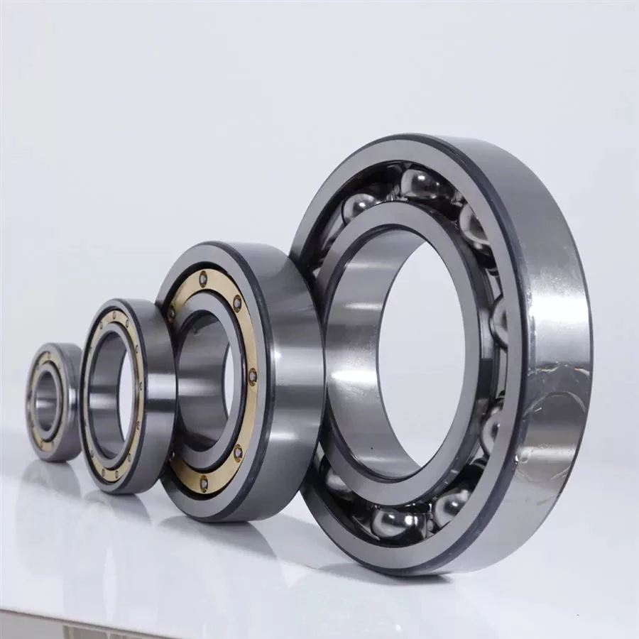
If you want to select a bearing for a specific application, you should know a few basics. This article will give you an overview of ball, angular contact, and sliding-contact bearings. You can choose a bearing according to the application based on the characteristics of its material and preload. If you are not sure how to choose a bearing, try experimenting with it. The next step is to understand the Z-axis, which is the axes along which the bearing moves.

Z axis

When it comes to replacing your Z axis bearing, there are several things you must know. First, you need to make sure that the bearings are seated correctly. Then, you should check the tension and rotation of each one. To ensure that both bearings are equally tensioned, you should flex the Core to the desired angle. This will keep the Z axis perpendicular to the work surface. To do this, first remove the Z axis bearing from its housing and insert it into the Z axis motor plate. Next, insert the flanged bearing into the Z axis motor plate and secure it with 2 M5x8mm button head cap screws.
Make sure that the bearing plate and the Z Coupler part are flush and have equal spacing. The spacing between the 2 parts is important, as too much spacing will cause the leadscrew to become tight. The screws should be very loose, with the exception of the ones that engage the nylocks. After installing the bearing, the next step is to start the Z axis. Once this is done, you'll be able to move it around with a stepper.

Angular contact

bearing
Ball bearings are made with angular contacts that result in an angle between the bearing's races. While the axial load moves in 1 direction through the bearing, the radial load follows a curved path, tending to separate the races axially. In order to minimize this frictional effect, angular contact bearings are designed with the same contact angle on the inner and outer races. The contact angle must be chosen to match the relative proportions of the axial and radial loads. Generally, a larger contact angle supports a higher axial load, while reducing radial load.
Ball bearings are the most common type of angular contact bearings. Angular contact ball bearings are used in many applications, but their primary purpose is in the spindle of a machine tool. These bearings are suitable for high-speed, precision rotation. Their radial load capacity is proportional to the angular contact angle, so larger contact angles tend to enlarge with speed. Angular contact ball bearings are available in single and double-row configurations.
Angular contact ball bearings are a great choice for applications that involve axial loads and complex shapes. These bearings have raceways on the inner and outer rings and mutual displacement along the axial axis. Their axial load bearing capacity increases as the contact Angle a rises. Angular contact ball bearings can withstand loads up to 5 times their initial weight! For those who are new to bearings, there are many resources online dedicated to the subject.
Despite their complexity, angular contact ball bearings are highly versatile and can be used in a wide range of applications. Their angular contact enables them to withstand moderate radial and thrust loads. Unlike some other bearings, angular contact ball bearings can be positioned in tandem to reduce friction. They also feature a preload mechanism that removes excess play while the bearing is in use.
Angular contact ball bearings are made with different lubricants and cage materials. Standard cages for angular contact ball bearings correspond to Table 1. Some are machined synthetic resins while others are molded polyamide. These cage materials are used to further enhance the bearing's axial load capacity. Further, angular contact ball bearings can withstand high speeds and radial loads. Compared to radial contact ball bearings, angular contact ball bearings offer the greatest flexibility.

Ball bearings

bearing
Ball bearings are circular structures with 2 separate rings. The smaller ring is mounted on a shaft. The inner ring has a groove on the outer diameter that acts as a path for the balls. Both the inner and outer ring surfaces are finished with very high precision and tolerance. The outer ring is the circular structure with the rolling elements. These elements can take many forms. The inner and outer races are generally made of steel or ceramic.
Silicon nitride ceramic balls have good corrosion resistance and lightweight, but are more expensive than aluminum oxide balls. They also exhibit an insulating effect and are self-lubricating. Silicon nitride is also suitable for high-temperature environments. However, this type of material has the disadvantage of wearing out rapidly and is prone to cracking and shattering, as is the case with bearing steel and glass. It's also less resistant to heat than aluminum oxide, so it's best to buy aluminum nitride or ceramic ball bearings for applications that are subjected to extremely high temperatures.
Another type of ball bearings is the thrust bearing. It has a special design that accommodates forces in both axial and radial directions. It is also called a bidirectional bearing because its races are side-by-side. Axial ball bearings use a side-by-side design, and axial balls are used when the loads are transmitted through the wheel. However, they have poor axial support and are prone to separating during heavy radial loads.
The basic idea behind ball bearings is to reduce friction. By reducing friction, you'll be able to transfer more energy, have less erosion, and improve the life of your machine. With today's advances in technology, ball bearings can perform better than ever before. From iron to steel to plastics, the materials used in bearings have improved dramatically. Bearings may also incorporate an electromagnetic field. So, it's best to select the right 1 for your machine.
The life expectancy of ball bearings depends on many factors, including the operating speed, lubrication, and temperature. A single million-rpm ball bearing can handle between 1 and 5 million rotations. As long as its surface contact area is as small as possible, it's likely to be serviceable for at least 1 million rotations. However, the average lifespan of ball bearings depends on the application and operating conditions. Fortunately, most bearings can handle a million or more rotations before they start showing signs of fatigue.

Sliding-contact bearings

bearing
The basic principle behind sliding-contact bearings is that 2 surfaces move in contact with 1 another. This type of bearing works best in situations where the surfaces are made of dissimilar materials. For instance, a steel shaft shouldn't run in a bronze-lined bore, or vice versa. Instead, 1 element should be harder than the other, since wear would concentrate in that area. In addition, abrasive particles tend to force themselves into the softer surface, causing a groove to wear in that part.
Sliding-contact bearings have low coefficients of friction and are commonly used in low-speed applications. Unlike ball and roller bearings, sliding contact bearings have to be lubricated on both sides of the contacting surfaces to minimize wear and tear. Sliding-contact bearings generally are made of ceramics, brass, and polymers. Because of their lower friction, they are less accurate than rolling-element bearings.
Sliding-contact bearings are also known as plain or sleeve bearings. They have a sliding motion between their 2 surfaces, which is reduced by lubrication. This type of bearing is often used in rotary applications and as guide mechanisms. In addition to providing sliding action, sliding-contact bearings are self-lubricating and have high load-carrying capacities. They are typically available in 2 different types: plain bearings and thrust bearings.
Sliding-contact linear bearing systems consist of a moving structure (called the carriage or slide) and the surfaces on which the 2 elements slide. The surfaces on which the bearing and journal move are called rails, ways, or guides. A bore hole is a complex geometry, and a minimum oil film thickness h0 is usually used at the line of centers. It is possible to have a sliding-contact bearing in a pillow block.
Because these bearings are porous, they can absorb 15 to 30% of the lubrication oil. This material is commonly used in automobile and machine tools. Many non-metallic materials are used as bearings. One example is rubber, which offers excellent shock absorbency and embeddability. While rubber has poor strength and thermal conductivity, it is commonly used in deep-well pumps and centrifugal pumps. This material has high impact strength, but is not as rigid as steel.

China factory Kehan Self-Propelled River Trash Skimmer Garbage Cleaning Boat Aquatic Weed Cleaning Boat Aquatic Weed Removal Machine Seaweed Water Hyacinth Harvester     near me shop China factory Kehan Self-Propelled River Trash Skimmer Garbage Cleaning Boat Aquatic Weed Cleaning Boat Aquatic Weed Removal Machine Seaweed Water Hyacinth Harvester     near me shop

China Professional 21V Cordless High Quality Flower Power Trimmers Machine Lithium Battery Grass Cutter TM-Lt12V302 near me shop

Product Description

1. Product Description:

Model number TM-LT21V1302
Lithium Battery 21V 2000mAh
Rated Power 650w
Motor type Brush motor
No-load speed 10000rpm
Cutting length 150mm
Telescope 90-130cm
Charging time 1.5hours
Working time 30-60mins

 2.Product Picture:

3.About us:

HangZhou Teamax Power Technology Co. Ltd specializes in producting various types of gardening and agriculture tools &machinery which 
mainly include brush cutters chainsaws lawn mowers.  Hedge trimmers earth aquer,  power spravers blower and so on. Our products are 
widely used in home & garden, public parks.sporting and agricultural land.With an enriched products portolio of features.sizes and uses. we can satisfy our clients requirements in  the work force or at home.
We have an advanced enterprise management philosophy and a strict quality control svstem .  Equipped with advanced inspection and 
testing facilities in the manufacturing process ,  we aim to provide high quality products for our giobal partners . Our technology centres 
have setup longterm strategic partnerships with several national professional organizations.We are committed to continuously enhanci
-ng the quality and performance of "TEAMAX" power  products, ensuring the company will always occupy the leading position in the ind
-ustry.

4.FAQ

1Q:Can I only buy spare parts ?
A: Yes, we can supply all spare parts and accessories for our products
2Q:Is it all right to make customer's own brand name
A: Sure,we can provide OEM
3Q: What are your payment terms?
A: T/T 30% deposit,70% balance against the copies of shipping documnets or L/C at sight
4.Q:How about quality control in your factory? 
A:"Quality is first, Customers are friends".
Every piece of goods is tested strictly one by one before packing and shipping. 
5Q:What is your deliver time ?
A: Within 25-30 days after got your  deposit.
6 Q: How would we get the detailed and accurate quotation?
A: Pumping medium, Flow rate, Head, Drive type,etc.
7Q: Is there any professional technical support?
A: The technical specialists group is available 24 hours a day. 7 days a week for your questions and problems.
8Q: How to guarantee the quality for your pumps?
 A: All of our products are approved by Iso// CE and also
 mill certificate and warranty data will be along with pumps.


How to Select a Worm Shaft and Gear For Your Project

You will learn about axial pitch PX and tooth parameters for a Worm Shaft 20 and Gear 22. Detailed information on these 2 components will help you select a suitable Worm Shaft. Read on to learn more....and get your hands on the most advanced gearbox ever created! Here are some tips for selecting a Worm Shaft and Gear for your project!...and a few things to keep in mind.
worm shaft

Gear 22

The tooth profile of Gear 22 on Worm Shaft 20 differs from that of a conventional gear. This is because the teeth of Gear 22 are concave, allowing for better interaction with the threads of the worm shaft 20. The worm's lead angle causes the worm to self-lock, preventing reverse motion. However, this self-locking mechanism is not entirely dependable. Worm gears are used in numerous industrial applications, from elevators to fishing reels and automotive power steering.
The new gear is installed on a shaft that is secured in an oil seal. To install a new gear, you first need to remove the old gear. Next, you need to unscrew the 2 bolts that hold the gear onto the shaft. Next, you should remove the bearing carrier from the output shaft. Once the worm gear is removed, you need to unscrew the retaining ring. After that, install the bearing cones and the shaft spacer. Make sure that the shaft is tightened properly, but do not over-tighten the plug.
To prevent premature failures, use the right lubricant for the type of worm gear. A high viscosity oil is required for the sliding action of worm gears. In two-thirds of applications, lubricants were insufficient. If the worm is lightly loaded, a low-viscosity oil may be sufficient. Otherwise, a high-viscosity oil is necessary to keep the worm gears in good condition.
Another option is to vary the number of teeth around the gear 22 to reduce the output shaft's speed. This can be done by setting a specific ratio (for example, 5 or 10 times the motor's speed) and modifying the worm's dedendum accordingly. This process will reduce the output shaft's speed to the desired level. The worm's dedendum should be adapted to the desired axial pitch.

Worm Shaft 20

When selecting a worm gear, consider the following things to consider. These are high-performance, low-noise gears. They are durable, low-temperature, and long-lasting. Worm gears are widely used in numerous industries and have numerous benefits. Listed below are just some of their benefits. Read on for more information. Worm gears can be difficult to maintain, but with proper maintenance, they can be very reliable.
The worm shaft is configured to be supported in a frame 24. The size of the frame 24 is determined by the center distance between the worm shaft 20 and the output shaft 16. The worm shaft and gear 22 may not come in contact or interfere with 1 another if they are not configured properly. For these reasons, proper assembly is essential. However, if the worm shaft 20 is not properly installed, the assembly will not function.
Another important consideration is the worm material. Some worm gears have brass wheels, which may cause corrosion in the worm. In addition, sulfur-phosphorous EP gear oil activates on the brass wheel. These materials can cause significant loss of load surface. Worm gears should be installed with high-quality lubricant to prevent these problems. There is also a need to choose a material that is high-viscosity and has low friction.
Speed reducers can include many different worm shafts, and each speed reducer will require different ratios. In this case, the speed reducer manufacturer can provide different worm shafts with different thread patterns. The different thread patterns will correspond to different gear ratios. Regardless of the gear ratio, each worm shaft is manufactured from a blank with the desired thread. It will not be difficult to find 1 that fits your needs.
worm shaft

Gear 22's axial pitch PX

The axial pitch of a worm gear is calculated by using the nominal center distance and the Addendum Factor, a constant. The Center Distance is the distance from the center of the gear to the worm wheel. The worm wheel pitch is also called the worm pitch. Both the dimension and the pitch diameter are taken into consideration when calculating the axial pitch PX for a Gear 22.
The axial pitch, or lead angle, of a worm gear determines how effective it is. The higher the lead angle, the less efficient the gear. Lead angles are directly related to the worm gear's load capacity. In particular, the angle of the lead is proportional to the length of the stress area on the worm wheel teeth. A worm gear's load capacity is directly proportional to the amount of root bending stress introduced by cantilever action. A worm with a lead angle of g is almost identical to a helical gear with a helix angle of 90 deg.
In the present invention, an improved method of manufacturing worm shafts is described. The method entails determining the desired axial pitch PX for each reduction ratio and frame size. The axial pitch is established by a method of manufacturing a worm shaft that has a thread that corresponds to the desired gear ratio. A gear is a rotating assembly of parts that are made up of teeth and a worm.
In addition to the axial pitch, a worm gear's shaft can also be made from different materials. The material used for the gear's worms is an important consideration in its selection. Worm gears are usually made of steel, which is stronger and corrosion-resistant than other materials. They also require lubrication and may have ground teeth to reduce friction. In addition, worm gears are often quieter than other gears.

Gear 22's tooth parameters

A study of Gear 22's tooth parameters revealed that the worm shaft's deflection depends on various factors. The parameters of the worm gear were varied to account for the worm gear size, pressure angle, and size factor. In addition, the number of worm threads was changed. These parameters are varied based on the ISO/TS 14521 reference gear. This study validates the developed numerical calculation model using experimental results from Lutz and FEM calculations of worm gear shafts.
Using the results from the Lutz test, we can obtain the deflection of the worm shaft using the calculation method of ISO/TS 14521 and DIN 3996. The calculation of the bending diameter of a worm shaft according to the formulas given in AGMA 6022 and DIN 3996 show a good correlation with test results. However, the calculation of the worm shaft using the root diameter of the worm uses a different parameter to calculate the equivalent bending diameter.
The bending stiffness of a worm shaft is calculated through a finite element model (FEM). Using a FEM simulation, the deflection of a worm shaft can be calculated from its toothing parameters. The deflection can be considered for a complete gearbox system as stiffness of the worm toothing is considered. And finally, based on this study, a correction factor is developed.
For an ideal worm gear, the number of thread starts is proportional to the size of the worm. The worm's diameter and toothing factor are calculated from Equation 9, which is a formula for the worm gear's root inertia. The distance between the main axes and the worm shaft is determined by Equation 14.
worm shaft

Gear 22's deflection

To study the effect of toothing parameters on the deflection of a worm shaft, we used a finite element method. The parameters considered are tooth height, pressure angle, size factor, and number of worm threads. Each of these parameters has a different influence on worm shaft bending. Table 1 shows the parameter variations for a reference gear (Gear 22) and a different toothing model. The worm gear size and number of threads determine the deflection of the worm shaft.
The calculation method of ISO/TS 14521 is based on the boundary conditions of the Lutz test setup. This method calculates the deflection of the worm shaft using the finite element method. The experimentally measured shafts were compared to the simulation results. The test results and the correction factor were compared to verify that the calculated deflection is comparable to the measured deflection.
The FEM analysis indicates the effect of tooth parameters on worm shaft bending. Gear 22's deflection on Worm Shaft can be explained by the ratio of tooth force to mass. The ratio of worm tooth force to mass determines the torque. The ratio between the 2 parameters is the rotational speed. The ratio of worm gear tooth forces to worm shaft mass determines the deflection of worm gears. The deflection of a worm gear has an impact on worm shaft bending capacity, efficiency, and NVH. The continuous development of power density has been achieved through advancements in bronze materials, lubricants, and manufacturing quality.
The main axes of moment of inertia are indicated with the letters A-N. The three-dimensional graphs are identical for the seven-threaded and one-threaded worms. The diagrams also show the axial profiles of each gear. In addition, the main axes of moment of inertia are indicated by a white cross.

China Professional 21V Cordless High Quality Flower Power Trimmers Machine Lithium Battery Grass Cutter TM-Lt12V302     near me shop China Professional 21V Cordless High Quality Flower Power Trimmers Machine Lithium Battery Grass Cutter TM-Lt12V302     near me shop