Tag Archives: machinery machinery

China Best Sales All-Terrain Vehicle/ATV Motorcycle Lawn Mowers Garden Machinery Rubber Fuel Line with Hot selling

Product Description

Product: All-Terrain Vehicle/ATV Motorcycle Lawn Mowers Garden Machinery Rubber Fuel Line
Item No.: JBD-E093
Size: ID ≥Φ2.5 mm;
Customized as Required.
Shape: Customized as Required.
Structure 1-4 Layers
Material: FKM/ECO;
FKM/ECO/YARN/ECO;
ACM/YARN/ACM;
NBR/YARN/CSM;
NBR/YARN/NBR+PVC;
NBR+PVC;
NBR+CSM/CM;
NBR; NR;ECO; ECO/CSM;
Structure: 1 to 4-layers
Color: Black
Application Use for Transmission System,Brake System, Clutch Lines,Fuel Supply System,Fuel Tank,Turbo Oil Feed Hose,Oil Pressure System, Gauge lines & Power Steering System in Engine, Motorcycle,Automobile,Trucks, Contruction Machinery,Heavy Equipments, Etc.
EPA & CARB CERTIFICATE YES.
Standard SAE, YDK,HES, EX-S,ASTM and so on
Shipping Port HangZhou 
OEM/ODM Accepted
Package PE bag+Carton+Pallet
Payment Terms T/T, L/C,Western Union
Factory ISO/TS16949:2009 registered
Technical Teams 30+ Years experience
Sample Leadtime 7-15 days
Production Leadtime 30-45 days

Structure of Hose
Our Company:

Product Development Procedure:

Test Equipment:

Our Unique Advantages:

A: 30+ Years Experienced Professional Technical Teams with strong R&D Center.
 
B: Powerful Capacity with 4 Production Factories Base.

C: Stable Quality and Competitive Price----We are an integrated company combining Rubber Raw Materials Refining & Mixer Process and manufacturing Rubber products with professional Technics, as well as Rubber Raw Materials Wholesales.

D: Good & In Time Service----all the enquiry will be processed within 24 hours with satisfactory service before and after sale.

E: Delivery time----15-20 days for mass production.

Certificate:

Process of Quality Control:

Products Collections

Packaging & Shipment

FAQ

Q1. Do your products have EPA/CARB Certificates?
 A. Yes, our products achieve EPA& CARB Certificates.
 

Q2.  Do your products meet RoHS?
Yes, all of our products are green products meet RoHS, REACH.

Q3.  Would you accept OEM/ODM ?
A.  Yes, OEM/ODM can be acceptable.  
Most of our products are customized and manufactured as per client's Drawings and Requirements.

Q4. Do you provide PPAP's ?
 A. Yes,  PPAP's is a basic documents under our IATF16949 certificate.

Q5.  What's the payment terms ?
A. T/T and L/C is acceptable .  30% downpayment and balance before shipments by T/T. Or 100% irrevocable LC at sight.  

Q6.  What kinds of materials are available to manufacture?
A. Our main Rubber & Plastic materials are NBR,SBR,NR,ACM,AEM,CSM,ECO,FKM,VMQ, EPDM,SILICONE,PVC,TPU,ect.


Pulley Type

There are several types of pulleys. These include fixed pulleys, load multipliers and movable pulleys. Below is a description of each pulley type. A load multiplier is a special type of pulley with multiple wheels for increased lifting capacity. It is used in a wide range of applications including power transmission and construction. Some common uses of pulleys are listed below.

moving pulley

Movable pulleys work by transferring the weight of a load to another object of the same mass. Since a live pulley is inherently frictionless and weightless, the force required to lift a load with it is the same as the weight of the load. This principle applies to tall buildings and residences. It is an excellent choice for lifting heavy objects such as furniture and washing machines.
A pulley is a mechanical device with a wheel that rotates on a shaft. The axle is attached to the wheel and is usually fixed. The movable pulley can be fixed or movable, both of which can change the direction of the force on the rope. Some pulleys can also change the magnitude and direction of the force. They are ideal for a variety of applications, from lifting heavy objects to transporting objects.
Another type of movable pulley works by transmitting force to another object. It has a free axis and the total force provided by the rope tension is balanced. Since the tension on the rope is constant in each segment, pulling 1 end of the rope will double the force on the shaft, resulting in 2 mechanical advantages. This mechanical advantage is the main reason why movable pulleys are so versatile.
Another form of moving pulley is called a KWL diagram. The KWL diagram summarizes the basic concepts of the drive wheel. KWL diagrams are an excellent way to assess a student's understanding of the concepts discussed in the course. Word questions are a great way to check whether students understand concepts. When students answer the word questions correctly, the answer is yes!
pulley

Fixed wheel pulley

If you need to move heavy objects, a single fixed wheel pulley is not a good choice. Using a single fixed pulley might be similar to using a handbag, but it's not very convenient. This type of pulley system relies on friction to transmit motion. As a result, it can slip and isn't always reliable. Fortunately, you can find other options that work just as well.
Fixed pulleys are the most basic type of pulley. They consist of grooved wheels and ropes attached to objects. These pulleys make lifting easier. Because the rope or cable only moves in 1 direction, the movement of the object feels lighter. And they are also easy to install. However, before you buy a fixed wheel pulley, make sure it is strong enough to support the weight of the load.
The disadvantages of fixed pulleys are obvious. One of them is the lack of mechanical advantage. A fixed pulley pulls up with the same force as a single moving pulley, and a single fixed pulley is not particularly effective as a force multiplier. However, the effect is more pronounced when you combine multiple fixed-wheel pulleys. You will get double the power! So what do fixed wheel pulleys have to offer?
Fixed wheel pulleys can be as small as a ring. A single ring pulley requires twice as much force as the weight being pulled. Adding more loops to the rope will reduce the effort required to pull the weight. The mechanical advantage of a fixed pulley is proportional to the number of strands running to the free pulley. A 100-pound pull on the free end will lift a 300-pound load.
pulley

composite pulley

Compound pulleys are pulleys that can be used to change the direction of a control wire. It can also be used to modify the mechanical force of the wire by moving the item it is connected to. In galleons, compound pulleys are more common. They are often combined with other ropes for mechanical advantage. Here are some common uses for composite pulleys.
The ideal mechanical advantage of a pulley is equal to the number of rope segments that pull up the load. This means that the more rope segments, the less force is required. A compound pulley will have the ideal mechanical advantage of 2, which means it will generate more force than a simple pulley. Composite pulleys are also more efficient at transmitting force because their number of rope segments is usually equal to the unit weight.
Composite pulley systems use more than 2 pulleys and ropes. More pulleys will reduce the force required to move heavier objects. They are usually used in large sailboats. The system is also used on construction sites. It can be used for a variety of applications, including lifting large objects or transmitting electricity. You can imagine how it would change your life if you had to move a large sailboat, but the result would be the same: a composite pulley system would make it easier to lift a large sailboat.
Composite pulleys are also known as fixed pulleys. The fixed pulley is stationary, and the movable pulley moves back and forth. The latter is more effective when used with a detachable cord or strap. On the other hand, a moving pulley is a moving pulley and it gives you a mechanical advantage. You can imagine this pulley on a flagpole.

load multiplier

The multiplication system has 3 basic parts: the rope grab, the connector, and the pulley. While some basic multipliers may combine the 3 parts, the concept remains the same. The multiplication system can make pulling the rope easier by reducing the amount of friction that occurs. Below are some examples of multiplication systems. A compact rope grab is a great option for resetting the multiplier.
The load reduction that a pulley system can achieve is proportional to the number of ropes used to support it. Although most utility pulley systems use only 4 ropes, the theoretical maximum load reduction is a quarter of the actual load. In other words, the four-wheel system only reduces the weight of a 1,000-pound load by a quarter. That would require 167 pounds of force, a far cry from the 500-pound load a single pulley system can achieve.
The mechanical advantage of a pulley system can be calculated by calculating the ratio between the forces exerted on each wire. For example, a 90-kilogram load is supported by 3 ropes, each weighing about 30-5 pounds. The ropes on pulleys A and B each carry a load of 60 kg. Using this formula, a single pulley system will yield a mechanical advantage over 2 tractors.
To calculate the force required to pull the rope over the pulley, measure the angle and deflection between the ropes. The deflection angle when added to the included angle should equal 180 degrees. A 75 degree angle requires 159% of the load force. This means a total load multiplier of four. This formula is an important tool for calculating the force multiple of the pulley.
pulley

Disadvantages of fixed pulleys

There are 2 basic types of pulleys: movable and fixed. Active pulleys are more advanced, allowing the pulley to move according to the load. They reduce the force required to lift the load. Active roller pulleys are more compact and therefore take up less space. Both types are good for lifting heavier objects, but they each have their pros and cons.
Fixed wheel pulleys can be used to lift heavy objects. This type of pulley consists of a wheel with a fixed shaft that has grooves on its edges for guiding ropes or cables. This is a simple machine as no motor or engine is required to lift objects. When 2 or more wheels are used together, the ropes around the wheels form a powerful hoist.
Single wheel pulleys are not suitable for lifting. They tend to push things down. Also, they are unreliable because they rely on friction and can slip. Also, a single wheel pulley would require a lot of space. Another disadvantage of fixed-wheel pulleys is that they make it difficult to move heavy objects easily. Single fixed-wheel pulleys also tend to slip easily, making them a poor choice for many applications.
Fixed wheel pulleys are also easier to install and maintain than manually operated ones. It requires less space and lubrication than manual pulleys. Manual pulleys can cause injury because the operator will be lifting the full weight of the heavy object. Additionally, rope slippage can lead to muscle strains and rope burns. And the system requires frequent maintenance.

China Best Sales All-Terrain Vehicle/ATV Motorcycle Lawn Mowers Garden Machinery Rubber Fuel Line     with Hot sellingChina Best Sales All-Terrain Vehicle/ATV Motorcycle Lawn Mowers Garden Machinery Rubber Fuel Line     with Hot selling

China Good quality All-Terrain Vehicle/ATV Motorcycle Lawn Mowers Garden Machinery Low Permeation Rubber Fuel Line near me shop

Product Description

Product: All-Terrain Vehicle/ATV Motorcycle Lawn Mowers Garden Machinery Low Permeation Rubber Fuel Line
Item No.: JBD-E095
Size: ID ≥Φ2.5 mm;
Customized as Required.
Shape: Customized as Required.
Structure 1-4 Layers
Material: FKM/ECO;
FKM/ECO/YARN/ECO;
ACM/YARN/ACM;
NBR/YARN/CSM;
NBR/YARN/NBR+PVC;
NBR+PVC;
NBR+CSM/CM;
NBR; NR;ECO; ECO/CSM;
Structure: 1 to 4-layers
Color: Black
Application Use for Transmission System,Brake System, Clutch Lines,Fuel Supply System,Fuel Tank,Turbo Oil Feed Hose,Oil Pressure System, Gauge lines & Power Steering System in Engine, Motorcycle,Automobile,Trucks, Contruction Machinery,Heavy Equipments, Etc.
EPA & CARB CERTIFICATE YES.
Standard SAE, YDK,HES, EX-S,ASTM and so on
Shipping Port HangZhou 
OEM/ODM Accepted
Package PE bag+Carton+Pallet
Payment Terms T/T, L/C,Western Union
Factory ISO/TS16949:2009 registered
Technical Teams 30+ Years experience
Sample Leadtime 7-15 days
Production Leadtime 30-45 days


Structure of Hose

Our Company:

Product Development Procedure:

Test Equipment:

Our Unique Advantages:

A: 30+ Years Experienced Professional Technical Teams with strong R&D Center.
 
B: Powerful Capacity with 4 Production Factories Base.

C: Stable Quality and Competitive Price----We are an integrated company combining Rubber Raw Materials Refining & Mixer Process and manufacturing Rubber products with professional Technics, as well as Rubber Raw Materials Wholesales.

D: Good & In Time Service----all the enquiry will be processed within 24 hours with satisfactory service before and after sale.

E: Delivery time----15-20 days for mass production.

Certificate:

Process of Quality Control:

Products Collections

Packaging & Shipment

FAQ

Q1. Do your products have EPA/CARB Certificates?
 A. Yes, our products achieve EPA& CARB Certificates.
 

Q2.  Do your products meet RoHS?
Yes, all of our products are green products meet RoHS, REACH.

Q3.  Would you accept OEM/ODM ?
A.  Yes, OEM/ODM can be acceptable.  
Most of our products are customized and manufactured as per client's Drawings and Requirements.

Q4. Do you provide PPAP's ?
 A. Yes,  PPAP's is a basic documents under our IATF16949 certificate.

Q5.  What's the payment terms ?
A. T/T and L/C is acceptable .  30% downpayment and balance before shipments by T/T. Or 100% irrevocable LC at sight.  

Q6.  What kinds of materials are available to manufacture?
A. Our main Rubber & Plastic materials are NBR,SBR,NR,ACM,AEM,CSM,ECO,FKM,VMQ, EPDM,SILICONE,PVC,TPU,ect.


Spiral Gears for Right-Angle Right-Hand Drives

Spiral gears are used in mechanical systems to transmit torque. The bevel gear is a particular type of spiral gear. It is made up of 2 gears that mesh with 1 another. Both gears are connected by a bearing. The 2 gears must be in mesh alignment so that the negative thrust will push them together. If axial play occurs in the bearing, the mesh will have no backlash. Moreover, the design of the spiral gear is based on geometrical tooth forms.
Gear

Equations for spiral gear

The theory of divergence requires that the pitch cone radii of the pinion and gear be skewed in different directions. This is done by increasing the slope of the convex surface of the gear's tooth and decreasing the slope of the concave surface of the pinion's tooth. The pinion is a ring-shaped wheel with a central bore and a plurality of transverse axes that are offset from the axis of the spiral teeth.
Spiral bevel gears have a helical tooth flank. The spiral is consistent with the cutter curve. The spiral angle b is equal to the pitch cone's genatrix element. The mean spiral angle bm is the angle between the genatrix element and the tooth flank. The equations in Table 2 are specific for the Spread Blade and Single Side gears from Gleason.
The tooth flank equation of a logarithmic spiral bevel gear is derived using the formation mechanism of the tooth flanks. The tangential contact force and the normal pressure angle of the logarithmic spiral bevel gear were found to be about 20 degrees and 35 degrees respectively. These 2 types of motion equations were used to solve the problems that arise in determining the transmission stationary. While the theory of logarithmic spiral bevel gear meshing is still in its infancy, it does provide a good starting point for understanding how it works.
This geometry has many different solutions. However, the main 2 are defined by the root angle of the gear and pinion and the diameter of the spiral gear. The latter is a difficult 1 to constrain. A 3D sketch of a bevel gear tooth is used as a reference. The radii of the tooth space profile are defined by end point constraints placed on the bottom corners of the tooth space. Then, the radii of the gear tooth are determined by the angle.
The cone distance Am of a spiral gear is also known as the tooth geometry. The cone distance should correlate with the various sections of the cutter path. The cone distance range Am must be able to correlate with the pressure angle of the flanks. The base radii of a bevel gear need not be defined, but this geometry should be considered if the bevel gear does not have a hypoid offset. When developing the tooth geometry of a spiral bevel gear, the first step is to convert the terminology to pinion instead of gear.
The normal system is more convenient for manufacturing helical gears. In addition, the helical gears must be the same helix angle. The opposite hand helical gears must mesh with each other. Likewise, the profile-shifted screw gears need more complex meshing. This gear pair can be manufactured in a similar way to a spur gear. Further, the calculations for the meshing of helical gears are presented in Table 7-1.
Gear

Design of spiral bevel gears

A proposed design of spiral bevel gears utilizes a function-to-form mapping method to determine the tooth surface geometry. This solid model is then tested with a surface deviation method to determine whether it is accurate. Compared to other right-angle gear types, spiral bevel gears are more efficient and compact. CZPT Gear Company gears comply with AGMA standards. A higher quality spiral bevel gear set achieves 99% efficiency.
A geometric meshing pair based on geometric elements is proposed and analyzed for spiral bevel gears. This approach can provide high contact strength and is insensitive to shaft angle misalignment. Geometric elements of spiral bevel gears are modeled and discussed. Contact patterns are investigated, as well as the effect of misalignment on the load capacity. In addition, a prototype of the design is fabricated and rolling tests are conducted to verify its accuracy.
The 3 basic elements of a spiral bevel gear are the pinion-gear pair, the input and output shafts, and the auxiliary flank. The input and output shafts are in torsion, the pinion-gear pair is in torsional rigidity, and the system elasticity is small. These factors make spiral bevel gears ideal for meshing impact. To improve meshing impact, a mathematical model is developed using the tool parameters and initial machine settings.
In recent years, several advances in manufacturing technology have been made to produce high-performance spiral bevel gears. Researchers such as Ding et al. optimized the machine settings and cutter blade profiles to eliminate tooth edge contact, and the result was an accurate and large spiral bevel gear. In fact, this process is still used today for the manufacturing of spiral bevel gears. If you are interested in this technology, you should read on!
The design of spiral bevel gears is complex and intricate, requiring the skills of expert machinists. Spiral bevel gears are the state of the art for transferring power from 1 system to another. Although spiral bevel gears were once difficult to manufacture, they are now common and widely used in many applications. In fact, spiral bevel gears are the gold standard for right-angle power transfer.While conventional bevel gear machinery can be used to manufacture spiral bevel gears, it is very complex to produce double bevel gears. The double spiral bevel gearset is not machinable with traditional bevel gear machinery. Consequently, novel manufacturing methods have been developed. An additive manufacturing method was used to create a prototype for a double spiral bevel gearset, and the manufacture of a multi-axis CNC machine center will follow.
Spiral bevel gears are critical components of helicopters and aerospace power plants. Their durability, endurance, and meshing performance are crucial for safety. Many researchers have turned to spiral bevel gears to address these issues. One challenge is to reduce noise, improve the transmission efficiency, and increase their endurance. For this reason, spiral bevel gears can be smaller in diameter than straight bevel gears. If you are interested in spiral bevel gears, check out this article.
Gear

Limitations to geometrically obtained tooth forms

The geometrically obtained tooth forms of a spiral gear can be calculated from a nonlinear programming problem. The tooth approach Z is the linear displacement error along the contact normal. It can be calculated using the formula given in Eq. (23) with a few additional parameters. However, the result is not accurate for small loads because the signal-to-noise ratio of the strain signal is small.
Geometrically obtained tooth forms can lead to line and point contact tooth forms. However, they have their limits when the tooth bodies invade the geometrically obtained tooth form. This is called interference of tooth profiles. While this limit can be overcome by several other methods, the geometrically obtained tooth forms are limited by the mesh and strength of the teeth. They can only be used when the meshing of the gear is adequate and the relative motion is sufficient.
During the tooth profile measurement, the relative position between the gear and the LTS will constantly change. The sensor mounting surface should be parallel to the rotational axis. The actual orientation of the sensor may differ from this ideal. This may be due to geometrical tolerances of the gear shaft support and the platform. However, this effect is minimal and is not a serious problem. So, it is possible to obtain the geometrically obtained tooth forms of spiral gear without undergoing expensive experimental procedures.
The measurement process of geometrically obtained tooth forms of a spiral gear is based on an ideal involute profile generated from the optical measurements of 1 end of the gear. This profile is assumed to be almost perfect based on the general orientation of the LTS and the rotation axis. There are small deviations in the pitch and yaw angles. Lower and upper bounds are determined as - 10 and -10 degrees respectively.
The tooth forms of a spiral gear are derived from replacement spur toothing. However, the tooth shape of a spiral gear is still subject to various limitations. In addition to the tooth shape, the pitch diameter also affects the angular backlash. The values of these 2 parameters vary for each gear in a mesh. They are related by the transmission ratio. Once this is understood, it is possible to create a gear with a corresponding tooth shape.
As the length and transverse base pitch of a spiral gear are the same, the helix angle of each profile is equal. This is crucial for engagement. An imperfect base pitch results in an uneven load sharing between the gear teeth, which leads to higher than nominal loads in some teeth. This leads to amplitude modulated vibrations and noise. In addition, the boundary point of the root fillet and involute could be reduced or eliminate contact before the tip diameter.

China Good quality All-Terrain Vehicle/ATV Motorcycle Lawn Mowers Garden Machinery Low Permeation Rubber Fuel Line     near me shop China Good quality All-Terrain Vehicle/ATV Motorcycle Lawn Mowers Garden Machinery Low Permeation Rubber Fuel Line     near me shop

China OEM EPA&Carb All-Terrain Vehicle/ATV Motorcycle Lawn Mowers Garden Machinery Rubber Fuel Line near me factory

Product Description

Product: EPA/Carb All-Terrain Vehicle/ATV Motorcycle Lawn Mowers Garden Machinery Rubber Fuel Line
Item No.: JBD-A034
Size: ID ≥Φ2.5 mm;
Customized as Required.
Material: FKM;
FKM/ECO;
FKM/ECO/AR/ECO
Structure: 1 to 4-layers
Color: Black
Application Use for All-Terrain Vehicle (ATV), Motorcycle,Outdoor Power Equipments,Agriculture Machinery, Garden Machinery,Off-Road Engines,Marine Engines and Generators.
EPA & CARB CERTIFICATE YES.
Standard SAE, SAE J1527,USCG,ASTM and so on
Shipping Port HangZhou 
OEM/ODM Accepted
Package PE bag+Carton+Pallet
Payment Terms T/T, L/C,Western Union
Factory ISO/IATF16949 registered
Technical Teams 30+ Years experience
Sample Leadtime 7-15 days
Production Leadtime 20-30 days

 
Structure of Hose

Our Company:

Product Development Procedure:

Test Equipment:

Our Unique Advantages:

A: 30+ Years Experienced Professional Technical Teams with strong R&D Center.
 
B: Powerful Capacity with 4 Production Factories Base.

C: Stable Quality and Competitive Price----We are an integrated company combining Rubber Raw Materials Refining & Mixer Process and manufacturing Rubber products with professional Technics, as well as Rubber Raw Materials Wholesales.

D: Good & In Time Service----all the enquiry will be processed within 24 hours with satisfactory service before and after sale.

E: Delivery time----15-20 days for mass production.

EPA & CARB Certificate:
Process of Quality Control

Products Collections

Packaging & Shipment

FAQ

Q1. Do your products have EPA/CARB Certificates?
 A. Yes, our products achieve EPA& CARB Certificates.
 

Q2.  Do your products meet RoHS?
Yes, all of our products are green products meet RoHS, REACH.

Q3.  Would you accept OEM/ODM ?
A.  Yes, OEM/ODM can be acceptable.  
Most of our products are customized and manufactured as per client's Drawings and Requirements.

Q4. Do you provide PPAP's ?
 A. Yes,  PPAP's is a basic documents under our IATF16949 certificate.

Q5.  What's the payment terms ?
A. T/T and L/C is acceptable .  30% downpayment and balance before shipments by T/T. Or 100% irrevocable LC at sight.  

Q6.  What kinds of materials are available to manufacture?
A. Our main Rubber & Plastic materials are NBR,SBR,NR,ACM,AEM,CSM,ECO,FKM,VMQ, EPDM,SILICONE,PVC,TPU,ect.


Screw Sizes and Their Uses

Screws have different sizes and features. This article will discuss screw sizes and their uses. There are 2 main types: right-handed and left-handed screw shafts. Each screw features a point that drills into the object. Flat tipped screws, on the other hand, need a pre-drilled hole. These screw sizes are determined by the major and minor diameters. To determine which size of screw you need, measure the diameter of the hole and the screw bolt's thread depth.

The major diameter of a screw shaft

The major diameter of a screw shaft is the distance from the outer edge of the thread on 1 side to the tip of the other. The minor diameter is the inner smooth part of the screw shaft. The major diameter of a screw is typically between 2 and 16 inches. A screw with a pointy tip has a smaller major diameter than 1 without. In addition, a screw with a larger major diameter will have a wider head and drive.
The thread of a screw is usually characterized by its pitch and angle of engagement. The pitch is the angle formed by the helix of a thread, while the crest forms the surface of the thread corresponding to the major diameter of the screw. The pitch angle is the angle between the gear axis and the pitch surface. Screws without self-locking threads have multiple starts, or helical threads.
The pitch is a crucial component of a screw's threading system. Pitch is the distance from a given thread point to the corresponding point of the next thread on the same shaft. The pitch line is 1 element of pitch diameter. The pitch line, or lead, is a crucial dimension for the thread of a screw, as it controls the amount of thread that will advance during a single turn.
screwshaft

The pitch diameter of a screw shaft

When choosing the appropriate screw, it is important to know its pitch diameter and pitch line. The pitch line designates the distance between adjacent thread sides. The pitch diameter is also known as the mean area of the screw shaft. Both of these dimensions are important when choosing the correct screw. A screw with a pitch of 1/8 will have a mechanical advantage of 6.3. For more information, consult an application engineer at Roton.
The pitch diameter of a screw shaft is measured as the distance between the crest and the root of the thread. Threads that are too long or too short will not fit together in an assembly. To measure pitch, use a measuring tool with a metric scale. If the pitch is too small, it will cause the screw to loosen or get stuck. Increasing the pitch will prevent this problem. As a result, screw diameter is critical.
The pitch diameter of a screw shaft is measured from the crest of 1 thread to the corresponding point on the next thread. Measurement is made from 1 thread to another, which is then measured using the pitch. Alternatively, the pitch diameter can be approximated by averaging the major and minor diameters. In most cases, the pitch diameter of a screw shaft is equal to the difference between the two.

The thread depth of a screw shaft

Often referred to as the major diameter, the thread depth is the outermost diameter of the screw. To measure the thread depth of a screw, use a steel rule, micrometer, or caliper. In general, the first number in the thread designation indicates the major diameter of the thread. If a section of the screw is worn, the thread depth will be smaller, and vice versa. Therefore, it is good practice to measure the section of the screw that receives the least amount of use.
In screw manufacturing, the thread depth is measured from the crest of the screw to the root. The pitch diameter is halfway between the major and minor diameters. The lead diameter represents the amount of linear distance traveled in 1 revolution. As the lead increases, the load capacity decreases. This measurement is primarily used in the construction of screws. However, it should not be used for precision machines. The thread depth of a screw shaft is essential for achieving accurate screw installation.
To measure the thread depth of a screw shaft, the manufacturer must first determine how much material the thread is exposed to. If the thread is exposed to side loads, it can cause the nut to wedge. Because the nut will be side loaded, its thread flanks will contact the nut. The less clearance between the nut and the screw, the lower the clearance between the nut and the screw. However, if the thread is centralized, there is no risk of the nut wedgeing.
screwshaft

The lead of a screw shaft

Pitch and lead are 2 measurements of a screw's linear distance per turn. They're often used interchangeably, but their definitions are not the same. The difference between them lies in the axial distance between adjacent threads. For single-start screws, the pitch is equal to the lead, while the lead of a multi-start screw is greater than the pitch. This difference is often referred to as backlash.
There are 2 ways to calculate the pitch and lead of a screw. For single-start screws, the lead and pitch are equal. Multiple-start screws, on the other hand, have multiple starts. The pitch of a multiple-start screw is the same as its lead, but with 2 or more threads running the length of the screw shaft. A square-thread screw is a better choice in applications requiring high load-bearing capacity and minimal friction losses.
The PV curve defines the safe operating limits of lead screw assemblies. It describes the inverse relationship between contact surface pressure and sliding velocity. As the load increases, the lead screw assembly must slow down in order to prevent irreversible damage from frictional heat. Furthermore, a lead screw assembly with a polymer nut must reduce rpm as the load increases. The more speed, the lower the load capacity. But, the PV factor must be below the maximum allowed value of the material used to make the screw shaft.

The thread angle of a screw shaft

The angle between the axes of a thread and the helix of a thread is called the thread angle. A unified thread has a 60-degree angle in all directions. Screws can have either a tapped hole or a captive screw. The screw pitch is measured in millimeters (mm) and is usually equal to the screw major diameter. In most cases, the thread angle will be equal to 60-degrees.
Screws with different angles have various degrees of thread. Originally, this was a problem because of the inconsistency in the threading. However, Sellers's thread was easier to manufacture and was soon adopted as a standard throughout the United States. The United States government began to adopt this thread standard in the mid-1800s, and several influential corporations in the railroad industry endorsed it. The resulting standard is called the United States Standard thread, and it became part of the ASA's Vol. 1 publication.
There are 2 types of screw threads: coarse and fine. The latter is easier to tighten and achieves tension at lower torques. On the other hand, the coarse thread is deeper than the fine one, making it easier to apply torque to the screw. The thread angle of a screw shaft will vary from bolt to bolt, but they will both fit in the same screw. This makes it easier to select the correct screw.
screwshaft

The tapped hole (or nut) into which the screw fits

A screw can be re-threaded without having to replace it altogether. The process is different than that of a standard bolt, because it requires threading and tapping. The size of a screw is typically specified by its major and minor diameters, which is the inside distance between threads. The thread pitch, which is the distance between each thread, is also specified. Thread pitch is often expressed in threads per inch.
Screws and bolts have different thread pitches. A coarse thread has fewer threads per inch and a longer distance between threads. It is therefore larger in diameter and longer than the material it is screwed into. A coarse thread is often designated with an "A" or "B" letter. The latter is generally used in smaller-scale metalworking applications. The class of threading is called a "threaded hole" and is designated by a letter.
A tapped hole is often a complication. There is a wide range of variations between the sizes of threaded holes and nut threads, so the tapped hole is a critical dimension in many applications. However, even if you choose a threaded screw that meets the requisite tolerance, there may be a mismatch in the thread pitch. This can prevent the screw from freely rotating.

China OEM EPA&Carb All-Terrain Vehicle/ATV Motorcycle Lawn Mowers Garden Machinery Rubber Fuel Line     near me factory China OEM EPA&Carb All-Terrain Vehicle/ATV Motorcycle Lawn Mowers Garden Machinery Rubber Fuel Line     near me factory

China Standard EPA/Carb Compliant Low Permeation Rubber Fuel Line for All-Terrain Vehicle/ATV Motorcycle Lawn Mowers Garden Machinery with Best Sales

Product Description

Products Details

Product: EPA/Carb Compliant Low Permeation Rubber Fuel Line All-Terrain Vehicle/ATV Motorcycle Lawn Mowers Garden Machinery
Item No.: JBD-A003
Size: ID ≥Φ2.5 mm;
Customized as Required.
Material: FKM;
FKM/ECO;
FKM/ECO/AR/ECO
Structure: 1 to 4-layers
Color: Black
Application Use for All-Terrain Vehicle (ATV), Motorcycle,Outdoor Power Equipments,Garden Machinery,Off-Road Engines,Marine Engines and Generators.
EPA & CARB CERTIFICATE YES.
Standard SAE, YDK,HES, EX-S,ASTM and so on
Shipping Port HangZhou 
OEM/ODM Accepted
Package PE bag+Carton+Pallet
Payment Terms T/T, L/C,Western Union
Factory ISO/IATF16949 registered
Technical Teams 30+ Years experience
Sample Leadtime 7-15 days
Production Leadtime 20-30 days


Structure of Hose

Our Company:

Product Development Procedure:

Test Equipment:

Our Unique Advantages:

A: 30+ Years Experienced Professional Technical Teams with strong R&D Center.
 
B: Powerful Capacity with 4 Production Factories Base.

C: Stable Quality and Competitive Price----We are an integrated company combining Rubber Raw Materials Refining & Mixer Process and manufacturing Rubber products with professional Technics, as well as Rubber Raw Materials Wholesales.

D: Good & In Time Service----all the enquiry will be processed within 24 hours with satisfactory service before and after sale.

E: Delivery time----15-20 days for mass production.

EPA & CARB Certificate:

Process of Quality Control

Products Collections

Packaging & Shipment

FAQ

Q1. Do your products have EPA/CARB Certificates?
 A. Yes, our products achieve EPA& CARB Certificates.
 

Q2.  Do your products meet RoHS?
Yes, all of our products are green products meet RoHS, REACH.

Q3.  Would you accept OEM/ODM ?
A.  Yes, OEM/ODM can be acceptable.  
Most of our products are customized and manufactured as per client's Drawings and Requirements.

Q4. Do you provide PPAP's ?
 A. Yes,  PPAP's is a basic documents under our IATF16949 certificate.

Q5.  What's the payment terms ?
A. T/T and L/C is acceptable .  30% downpayment and balance before shipments by T/T. Or 100% irrevocable LC at sight.  

Q6.  What kinds of materials are available to manufacture?
A. Our main Rubber & Plastic materials are NBR,SBR,NR,ACM,AEM,CSM,ECO,FKM,VMQ, EPDM,SILICONE,PVC,TPU,ect.


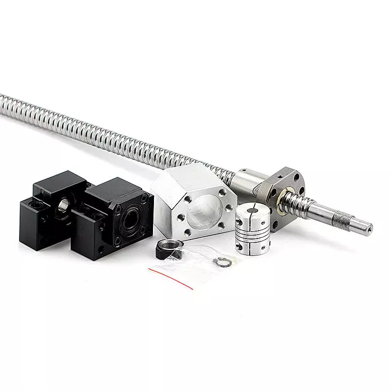
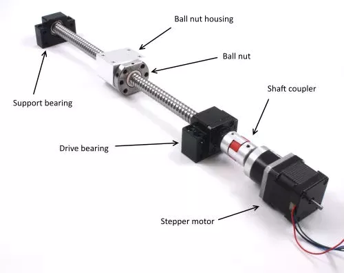
Supporting Ball Screws

In order to use a ball screw in a project, it is important to support it for rotation. Typically, this requires holding brackets and roller bearings. Longer screws may require bending or critical speed restraints. End machining may be necessary to fit the screw into the bearing. Connection to a motor requires coupling and appropriate machining. Tables or support rails may be necessary to restrain the nut.

Cost

In this report, you'll get an in-depth analysis of the ball screw market. You'll learn about the competitive landscape, product portfolio, and growth prospects across regions. The report will also include information on the market's various drivers and restraints, as well as the factors driving or restraining its development. You'll also get an in-depth look at the value chain and PEST analysis, which are important components of a market study.
One resource that you can use to research the Ball Screw market is CZPT. This website contains a database of authentic Indian manufacturers, suppliers, and importers. You'll find contact details and email addresses of the companies, including those that produce a wide variety of different types of ball screws. CZPT even allows you to search by product category. That way, you can find a supplier based on the type of ball screw you need at the lowest price.
Another benefit of ball screws is their ability to operate in very delicate applications. In electric vehicles, they are often used to replace a common hydraulic system. They are also used to control gates at hydroelectric stations. You can also find them in motorised inspection tables, step photolithography machines, and microscopic integrated circuits. You can find hundreds of different ball screw designs, and you can even purchase them with nuts, wipers, and CZPT. Ball screws have several bearing balls, which help transfer load between nut and screw. They can be available with adjustable preload and non-preloaded options. And they're manufactured to industry standards to meet the demands of their users.
If you're looking for a reliable, high-performing screw, you'll want to opt for a ball screw. These have high performance-to-cost ratios. You'll need to choose between a lead screw and a ball screw, but both are reliable and efficient. Besides, the former is less expensive and offers great design flexibility. They're corrosion-resistant and can even be self-locking for vertical applications.
air-compressor

Applications

A ball screw and nut assembly are essential components of a variety of important actuation and control devices. The 2 components rely on the ability of the screw to rotate easily while converting the rotation into precise lateral movement. Ball screws are a common component in computer-controlled motion-control systems. The precision of ball screw rotation is essential for the accurate adjustment of flight control surfaces. In addition, ball screws are important components of wire bonding and computer-controlled motion-control systems.
Ball screws are highly accurate, requiring minimal lead error. The lead error of a screw is the difference between the theoretical and actual distance traveled by the nut during rotation. The lead error of a ball screw depends on several factors, including the manufacturing accuracy of the ball grooves, the compactness of the assembly, and the set-up precision. This error is not constant from lead to lead, but it may be reduced through preloading, lubrication, and increased mounting accuracy.
The ball is urged to move up and down by rotation of the nut, which is preferably a hexagonal shaft. This allows the ball to be raised easily over the land of the screw. It is important to note that the nut has a groove on the outer surface that is deep enough to accommodate a ball. This groove is deep enough to accommodate a ball, and the groove extends the length of the screw, thereby reducing friction and increasing precision.
The recirculated balls in a multi-start ball screw assembly may cross multiple threads and turn in the circuit. Multi-start ball screw assemblies typically use the internal channel method to recirculate balls. This design allows multiple ball nuts to be used in a single nut and can be easily installed. The ball nut and the nut may also be incorporated into several separate circuits. If several recirculation paths are desired, a ball nut and a multi-start system may be used.

Durability

A key feature of ball screws is their durability. During manufacture, a ball screw's material must be chosen carefully. A corrosion-resistant steel called Cronidur(r) 30 is an ideal choice. Ball screws made from this material are exceptionally reliable in space due to their alternating steel-ceramic architecture. As the conditions of space are extreme, corrosion-resistant materials are essential to ensure optimum performance. CZPT has decades of experience manufacturing high-quality ball screws. Besides providing a complete range of ball screws, the company also offers technological solutions and dedicated components.
CZPT developed a special design for the High-Durability Precision Ball Screw. This design makes it easier to form a thin film of oil on the material's surface. This oil helps reduce friction and improve the precision of a ball screw. This material's special microstructure reduces the wear of ball screws and improves their service life. CZPT also aims to improve the wear-resistance of ball screws.
In addition to the axial load, a ball screw's life rating should be based on the jacking and vertical loads. In other words, if all load balls are in contact with the raceways, the L-10 life rating of ball screw assemblies would be converted to an L-2 life rating. This change would increase the overall reliability of a ball screw to 98%. Then again, it's important to note that vertical load is the only 1 that would be completely removed from the chart.
In addition to these important considerations, it is essential to operate ball screws within their recommended operating temperature range. Failure to do so could result in thermal expansion of the ball screw, causing positioning errors. To ensure lubrication of the ball screw, it's important to keep its operating temperature within the recommended range. However, it is possible to operate it at temperatures that are too high. If this occurs, the screw should be sent to the manufacturer for repair.
air-compressor

Size

Besides their obvious use, ball screws come in 2 sizes, large and small. Although small balls should not show significant wear, they should still be used to enhance the screw's durability. This can be difficult to determine because screw rebuilders tend to overlook this aspect. So, what is the best size for ball screws? This article will look at both sizes and what they mean for the screw's durability. Also, we'll look at some of the things to keep in mind when choosing the right size for your project.
A ball screw's size depends on its application and performance requirements. Some types have small diameters and fine leads, while others feature large diameters. High precision applications often require miniature ball screws. Some manufacturers even offer compact ball screws with a smaller outer diameter. The latter is commonly found in miniature designs and feature diameters up to 25 mm. However, this doesn't mean that a smaller diameter means less accuracy. Regardless of the size, you'll want to make sure to select a screw that will meet your requirements.
The screw's root diameter is a critical measurement in determining critical speed and column load calculations. A ball screw's minor diameter is the minimum dimension of the screw shaft at the bottom of the ball grooves. In addition, the idler ball is a necessary component of a ball screw. It prevents friction between the load and idler balls, but does not carry the load itself. Likewise, the non-operating load capacity should be large enough to prevent the balls from brinelling and plastic deformation.
The characteristic speed is the rotational speed at which the ball screw begins to vibrate due to dynamic load. Inch/imperial screws are specified for 1 million revolutions, while metric screw has a specific limit for 1 million inches of linear travel. Various manufacturing processes have their own ways to calculate the useful life of ball screw assemblies. For example, Precision Grinding produces the lowest lead errors. In addition, the life of a ball screw depends on the length of the screw and the mounting support for the end bearings.
air-compressor

Maintenance

It is critical to regularly perform PM on your ball screw assemblies to ensure optimal performance. A dirty ball screw assembly will result in poor performance and faster wear, so removing dirt from the nut and shaft is a good idea. If there are problems with the ball nut, the lubricant inside can become stripped or the nut can become dirty due to chemical exposure. You should also check for oxidation or corrosion on the contact surfaces of the ball screw, and replace it if necessary.
The first sign of a deteriorating ball screw is excessive vibration. This may be caused by a bent screw shaft or misaligned bearing housings. If it makes noise when running, this may be due to excessive build-up or a broken return tube. Other issues may be caused by endplay in support bearings or excessive preload or improper lubrication. If any of these problems are found, it is essential to perform regular maintenance on the ball screw to prolong its life.
Getting regular maintenance on the ball screw assembly is important. If the screw is not properly maintained, it may wear out prematurely. If this happens, you can contact a ball screw repair service. CZPT International, Inc., a leading supplier of industrial parts, can help you get the screw back into optimal working order or find a new one. A ball screw repair company can help you avoid the inconvenience of downtime and maximize your productivity.
It is essential to properly lubricate a ball screw assembly in order to prolong its life. Lubrication can prevent corrosion and increase the life of the screw by 85 percent. It is important to remember that the type of lubricant you use should correspond to the load applied to the assembly. Lubrication should also be done at regular intervals. Once you've established the right amount of lubrication, you can then apply it on the screw.

China Standard EPA/Carb Compliant Low Permeation Rubber Fuel Line for All-Terrain Vehicle/ATV Motorcycle Lawn Mowers Garden Machinery     with Best SalesChina Standard EPA/Carb Compliant Low Permeation Rubber Fuel Line for All-Terrain Vehicle/ATV Motorcycle Lawn Mowers Garden Machinery     with Best Sales