Tag Archives: motor hydraulic

China Good quality Hydraulic Motor A6vm80/A6vm107/A6vm140 for Construction Equipment/Loader/Excavator/Bulldozer/Overhead Crane Spare Parts with high quality

Product Description

Product Description

A2FO, A2FE, A2FM, A4FM, A4VG, A4VSG, A4CSG, A4VSO, A6VM, A6VE, A7VO, A8VO, A10VG, A10VO, A10VSO, A11VO, A11VLO, A15VSO, A20VG, A22VG offered by LOYAL Hydraulics Co., Ltd

Detailed Photos

Packaging & Shipping

1.Standard exporting wooden case by Sea, while carton boxes by Air or Express. Besides, customized packing acceptable.
2.In stock, within 2-3 days after payments. Out of stock, we will prepare it to in 15 days, which is very seldom taken place in LOYAL.

Company Profile

LOYAL Hydraulic is a professional manufacture of replacement precision parts for Caterpillar, Rexroth, Kawasaki, Komatsu, Linde, Sauer Sundstrand, Eaton, KYB, Bobcat, Parker/Denison,Nabtesco,HAWE, Yuken, Poclain, Hagglunds hydraulic piston pump, vane pump,gear pump ,hydraulic motor and hydraulic valve in China. If you choose our products, you will low your cost about excavator main pump maintenance ,hydraulic system, repairing definitely.

Our Advantages

1.Highest quality warranty with the most favorable price.
2.80% of our employees are skillful technicians and mechanics.
3.All goods will be tested before shipping,1 A6VM140EP2D/63W-VZB571FHB R957186~8 A6VM140EP2D/63W-VZB571FHB-K R957114725 A6VM140EP2D/63W-VZB571HHB R957188590 A6VM140EP2D/63W-VZB571PB R957182018 A6VM140EP2D/63W-VZB380FHB-S R957182016 A6VM140EP2D/63W-VZB380FHB-SK R957127755 A6VM140EP2D/63W-VZB388HHB R957133206 A6VM140EP2D/63W-XAB571B-S R957160490 A6VM140EP2DX/63W-VZB571DHB-S R957160488 A6VM140EP2DX/63W-VZB571DHB-SK R957114728 A6VM140EP2DX/63W-VZB571IHB-S R957168767 A6VM140EP2DX/63W-VZB380HB-S R957168765 A6VM140EP2DX/63W-VZB380HB-SK R957115719 A6VM140EP2DX/63W-VZB380PB-S R957117976 A6VM140EP2DX/63W-VZB380PB-S R957157148 A6VM140EP2DX/63W-VZB380PB-S R957157152 A6VM140EP2DX/63W-VZB380PB-S R957157146 A6VM140EP2DX/63W-VZB380PB-SK R957117974 A6VM140EP2DX/63W-VZB380PB-SK R957115718 A6VM140EP2DX/63W-VZB380PB-SK R957117975 A6VM140EP2DX/63W-VZB380PB-SK R957115837 A6VM140EP2DX/63W-VZB380PB-SK R957157151 A6VM140EP2DX/63W-VZB380PB-SK R957173746 A6VM140EP2E/63W-VZB571HB R957148293 A6VM140EP500P000F/65MWV0R4A110V-Y R957145905 A6VM140EP600H001E/65MWV0R4A11K0-0 R957145906 A6VM140EP600H001E/65MWV0R4A11K0-0 R957160405 A6VM140EP600P000A/65MWV0R4A11D0-0 R957177285 A6VM140EP600P000X/65MWV0R4A11GV-S R957177284 A6VM140EP600P000X/65MWV0R4A11GV-S R957175047 A6VM140EP6D1P001C/65MWV0R4A1200-0 R957171708 A6VM140EP7/63W-VZB571DA R957154985 A6VM140EP7/63W-VZB571DHA R957116562 A6VM140EP7/63W-VZB571DHA R957133693 A6VM140EPM/63W-VZBXX7FPB-S R957157668 A6VM140EPP00P000E/65CWV0R4A11IF-S R957143026 A6VM140EPU/63W-VAB5710LB R957141925 A6VM140EPU/63W-VAB5710LB R957147458 A6VM140EPUD/63W-VAB5710LB R957101413 A6VM140EPX/63W-VZB017FXB-S R957188958 A6VM140EPX/63W-VZBXX7FPB-S R99205717 A6VM140EPX/63W-VZBXX7FPB-S R957135490 A6VM140EPX/63W-VZBXX7FPB-S R957188957 A6VM140EPX/63W-VZBXX7FPB-S R98611 0571 A6VM140EPX/63W-VZBXX7FPB-S R99205716 A6VM140EPX/63W-VZBXX7FPB-S R986110526 A6VM140EPX/63W-VZBXX7FPB-S R986120008 A6VM140EPX/63W-VZBXX7FPB-S REMAN R986120009 A6VM140EPX/63W-VZBXX7FPB-S REMAN R957199078 A6VM140EPX/63W-VZBXX7FXB-S R957199082 A6VM140EPX/63W-VZBXX7FXB-S R957163521 A6VM140EPX/63W-VZBXXXFXB-S R957153711 A6VM140EPX/63W-VZBXXXFXB-S R957153704 A6VM140EPX/63W-VZBXXXFXB-SK R957153709 A6VM140EPX/63W-VZBXXXFXB-SK R957143166 A6VM140EPX00P000E/65CWV0R4A11IF-S R957142287 A6VM140EZ1/63W-VZB017B R957190343 A6VM140EZ1/63W-VZB017HA R957152450 A6VM140EZ1/63W-VZB017HB R909605650 A6VM140EZ1/63W-VZB571B R957152446 A6VM140EZ1/63W-VZB571HB R957170544 A6VM140EZ1/63W-VZB5710PB R957149354 A6VM140EZ1/63W-VZB571A R957118313 A6VM140EZ1/63W-VZB571B R957152455 A6VM140EZ1/63W-VZB571HA R957152458 A6VM140EZ1/63W-VZB571HB R957196860 A6VM140EZ1/63W-VZB571PB R957151613 A6VM140EZ100P001X/65MWV0D4XX1K0-S R957137196 A6VM140EZ2/63W-VZB5710PB R95718 0571 A6VM140EZ2/63W-VZB571HB R957135230 A6VM140EZ2/63W-VZB017B R957152453 A6VM140EZ2/63W-VZB017HB R90961571 A6VM140EZ2/63W-VZB571B R957118430 A6VM140EZ2/63W-VZB571DB R957118429 A6VM140EZ2/63W-VZB571DB-K R957152449 A6VM140EZ2/63W-VZB571HB R957152443 A6VM140EZ2/63W-VZB571HDB R957168894 A6VM140EZ2/63W-VZB571WB R957100073 A6VM140EZ2/63W-VZB571B R957152459 A6VM140EZ2/63W-VZB571HB R957101611 A6VM140EZ2/63W-VZB571PB R957126536 A6VM140EZ2/63W-VZB380PB-S R957126534 A6VM140EZ2/63W-VZB380PB-SK R957127657 A6VM140EZ2/63W-VZB3880PB R957150565 A6VM140EZ500P001F/65MWV0R4A12D0-0 R95715 0571 A6VM140EZ600P001F/65MWV0R4A12D0-0 R957107856 A6VM140HA1/63W-VAB571A-E R957163781 A6VM140HA1/63W-VAB571A R957149452 A6VM140HA1/63W-VXB571A-S R992001704 A6VM140HA1/63W-VZB57100A R957112081 A6VM140HA1/63W-VZB57100A R957126183 A6VM140HA1/63W-VZB57100A R992000017 A6VM140HA1/63W-VZB571A R957114156 A6VM140HA1/63W-VZB571A R90961571 A6VM140HA1/63W-VZB571A R957130605 A6VM140HA1/63W-VZB571A R957132448 A6VM140HA1/63W-VZB380A R957132445 A6VM140HA1/63W-VZB380A-K R957138801 A6VM140HA1R1/63W-VAB571A R957154170 A6VM140HA1R1/63W-VAB571HA R957116561 A6VM140HA1R1/63W-VZB0170HA R992001700 A6VM140HA1R1/63W-VZB0170HA R909604955 A6VM140HA1R1/63W-VZB017A R957114259 A6VM140HA1R1/63W-VZB017A-S R957154164 A6VM140HA1R1/63W-VZB017HA R992000095 A6VM140HA1R1/63W-VZB017HA R957116971 A6VM140HA1R1/63W-VZB01X0HA-S R957101590 A6VM140HA1R1/63W-VZB01X0HA-S R957116505 A6VM140HA1R1/63W-VZB01X0HA-S R957114748 A6VM140HA1R1/63W-VZB01X0HA-S R957114324 A6VM140HA1R1/63W-VZB01XA-S R95717144 A6VM140HA1R1/63W-VZB01XHA-S R986110667 A6VM140HA1R1/63W-VZB01XHA-S R957163747 A6VM140HA1R1/63W-VZB01XHA-S R986100629 A6VM140HA1R1/63W-VZB01XHA-S REMAN R986100629 A6VM140HA1R1/63W-VZB01XHA-S REMAN R986120634 A6VM140HA1R1/63W-VZB01XHA-S REMAN R95718571 A6VM140HA1R1/63W-VZB571HA R957145954 A6VM140HA1R1P005B/65MWV0R4A11C0-0 R957151515 A6VM140HA1R1P005B/65MWV0R4A11E0-0 R957180617 A6VM140HA1R1X/63W-VZB01XHA-S R957186759 A6VM140HA1R2/63W-VAB571TA R957116525 A6VM140HA1R2/63W-VXB0170CA-S R957111629 A6VM140HA1R2/63W-VXB0170CA-S R957175289 A6VM140HA1R2/63W-VXB017CA-S R957121762 A6VM140HA1R2/63W-VXB017CA-S R902602617 A6VM140HA1R2/63W-VXB017CA-S R992000499 A6VM140HA1R2/63W-VXB017CA-S R957100491 A6VM140HA1R2/63W-VZB017PA R957186726 A6VM140HA1R2/63W-VZB01XDHA-S R957186724 A6VM140HA1R2/63W-VZB01XDHA-SK R957167822 A6VM140HA1R2/63W-VZB01XHA-S R957124460 A6VM140HA1R2/63W-VZB5710XA-S R90961571 A6VM140HA1R2/63W-VZB571A R957127072 A6VM140HA1R2/63W-VZB571A-S R957154161 A6VM140HA1R2/63W-VZB571HA R957163743 A6VM140HA1R2/63W-VZB571HA-S R957100164 A6VM140HA1R2/63W-VZB571XA-ES R99200 0571 A6VM140HA1R2/63W-VZB571XA-ES R90961 0571 A6VM140HA1R2/63W-VZB571A R957186903 A6VM140HA1R2/63W-VZB571FHA R957186901 A6VM140HA1R2/63W-VZB571FHA-K R957196944 A6VM140HA1R2/63W-VZB571FPA R957196949 A6VM140HA1R2/63W-VZB571FPA-K R957154167 A6VM140HA1R2/63W-VZB571HA R957170118 A6VM140HA1R2/63W-VZB571PA R957188728 A6VM140HA1R2/63W-VZB571TA R957116547 A6VM140HA1R2/63W-VZB02X0XA-S R957116534 A6VM140HA1R2/63W-VZB02X0XA-S R957124458 A6VM140HA1R2/63W-VZB02X0XA-S R957114395 A6VM140HA1R2/63W-VZB02XA-S R992000164 A6VM140HA1R2/63W-VZB02XHA-S R957163745 A6VM140HA1R2/63W-VZB02XHA-S R957100162 A6VM140HA1R2/63W-VZB02XXA-ES R99200 0571 A6VM140HA1R2/63W-VZB02XXA-ES R9920571 A6VM140HA1R2/63W-VZB02XXA-ES R957100145 A6VM140HA1R2/63W-VZB02XXA-ES R957149007 A6VM140HA1T/63W-VZB571A R95715710 A6VM140HA1T/63W-VZB571A R957170589 A6VM140HA1T/63W-VZB57100A R957116512 A6VM140HA1T/63W-VZB57100A R957170586 A6VM140HA1T/63W-VZB57100A R957180884 A6VM140HA1T/63W-VZB571A R957163528 A6VM140HA1T/63W-VZB571FA R957163526 A6VM140HA1T/63W-VZB571FA-K R957116772 A6VM140HA1T/63W-VZB38000A-Y R957116763 A6VM140HA1T/63W-VZB38000A-Y R957112101 A6VM140HA1T/63W-VZB38000A-Y R957116773 A6VM140HA1T/63W-VZB38000A-Y R957116774 A6VM140HA1T/63W-VZB38000A-Y R957116924 A6VM140HA1T/63W-VZB38000A-Y R957100163 A6VM140HA1T/63W-VZB380A R99200571 A6VM140HA1T/63W-VZB380A-ESK R95715717 A6VM140HA1T/63W-VZB380A-ESK R957153667 A6VM140HA1T/63W-VZB380A-ESK R957186214 A6VM140HA1T/63W-VZB380A-ESK R957124131 A6VM140HA1T/63W-VZB380A-ESK R957126880 A6VM140HA1T/63W-VZB380A-ESK R957153663 A6VM140HA1T/63W-VZB380A-ESK R957186216 A6VM140HA1T/63W-VZB380A-ESK R957127571 A6VM140HA1T/63W-VZB380A-K R957100161 A6VM140HA1T/63W-VZB380A-K R957114473 A6VM140HA1T/63W-VZB380A-K R957138998 A6VM140HA1T/63W-VZB380A-K R95717571 A6VM140HA1T/63W-VZB380A-K R957140165 A6VM140HA1T/63W-VZB380A-K R95713 0571 A6VM140HA1T/63W-VZB380A-K R95715719 A6VM140HA1T/63W-VZB380A-S R957194711 A6VM140HA1T/63W-VZB380A-SK R957186835 A6VM140HA1T/63W-VZB380A-SK R95717128 A6VM140HA1T/63W-VZB380A-SK R987395713 A6VM140HA1T/63W-VZB380A-SK + BVD25F38S/4 R957163758 A6VM140HA1T/63W-VZB380DA R957194558 A6VM140HA1T/63W-VZB380DA-K R957163757 A6VM140HA1T/63W-VZB380DA-K R9571 0571 9 A6VM140HA1T/63W-VZB38800A R957112088 A6VM140HA1T/63W-VZB38800A R957112086 A6VM140HA1T/63W-VZB38800A R957116531 A6VM140HA1T/63W-VZB38800A R957121955 A6VM140HA1T/63W-VZB38800A R957117835 A6VM140HA1T/63W-VZB38800A R957116533 A6VM140HA1T/63W-VZB38800A-S R957116542 A6VM140HA1T/63W-VZB38800A-S R957103600 A6VM140HA1T/63W-VZB38800A-S R957116548 A6VM140HA1T/63W-VZB38800A-S R957116543 A6VM140HA1T/63W-VZB38800A-S R957103606 A6VM140HA1T/63W-VZB38800A-S R957115319 A6VM140HA1T/63W-VZB38800A-S R957124451 A6VM140HA1T/63W-VZB38800A-S R957124450 A6VM140HA1T/63W-VZB38800A-S R957114731 A6VM140HA1T/63W-VZB388I0A R957157654 A6VM140HA1T30001E/65MWV0R4A18W0-0 R957141988 A6VM140HA1T30001E/65MWV0R4A18W0-0 R957147314 A6VM140HA1T30001G/65MWV0R4A18W0-0 R957152252 A6VM140HA1TA/63W-VXB380A-S R957152248 A6VM140HA1TA/63W-VXB380A-S R957143949 A6VM140HA1TA/63W-VXB380A-S R957152246 A6VM140HA1TA/63W-VXB380A-SK R957152250 A6VM140HA1TA/63W-VXB380A-SK R957143950 A6VM140HA1TA/63W-VXB380A-SK R957112097 A6VM140HA1TA/63W-VZB38000A R957163803 A6VM140HA1TA/63W-VZB380A-S R957172617 A6VM140HA1TA/63W-VZB380A-S R957157281 A6VM140HA1TA/63W-VZB380A-S R957184207 A6VM140HA1TA/63W-VZB380A-S R957143702 A6VM140HA1TA/63W-VZB380A-S R957163926 A6VM140HA1TA/63W-VZB380A-S R957117597 A6VM140HA1TA/63W-VZB380A-S R95714 0571 A6VM140HA1TA/63W-VZB380A-S R957117595 A6VM140HA1TA/63W-VZB380A-SK R95713571 A6VM140HA1TA/63W-VZB380A-SK R957143703 A6VM140HA1TA/63W-VZB380A-SK R957188940 A6VM140HA1TA/63W-VZB380A-SK R957157279 A6VM140HA1TA/63W-VZB380A-SK R957188935 A6VM140HA1TA/63W-VZB380A-SK R957167891 A6VM140HA1TA/63W-VZB380A-SK R957140484 A6VM140HA1TA/63W-VZB380A-SK R957184205 A6VM140HA1TA/63W-VZB380A-SK R957163801 A6VM140HA1TA/63W-VZB380A-SK R957163925 A6VM140HA1TA/63W-VZB380A-SK R957112100 A6VM140HA1TA/63W-VZB38800A R957114717 A6VM140HA1TA/63W-VZB38800A R957114727 A6VM140HA1TA/63W-VZB38800A-S R957167890 A6VM140HA1TA/63W-VZB38800A-S R95715711 A6VM140HA1TA/63W-VZB38800A-S R957126878 A6VM140HA1TB/63W-VZB380A-ESK R99200571 A6VM140HA1TB/63W-VZB380A-ESK R957153661 A6VM140HA1TB/63W-VZB380A-ESK R957186222 A6VM140HA1TB/63W-VZB380A-ESK R99200571 A6VM140HA1TB/63W-VZB380A-ESK R957115714 A6VM140HA1TB/63W-VZB380A-ESK R957186219 A6VM140HA1TB/63W-VZB380A-ESK R957153665 A6VM140HA1TB/63W-VZB380A-ESK R957126882 A6VM140HA1TB/63W-VZB380A-ESK R957101442 A6VM140HA1TB/63W-VZB380A-S R957196888 A6VM140HA1TB/63W-VZB380A-S R957180521 A6VM140HA1TB/63W-VZB380A-S R957101439 A6VM140HA1TB/63W-VZB380A-SK R957196884 A6VM140HA1TB/63W-VZB380A-SK R95718571 A6VM140HA1TB/63W-VZB380A-SK R95717126 A6VM140HA1TB/63W-VZB380A-SK R957114711 A6VM140HA1TB/63W-VZB38800A R957139984 A6VM140HA1TB/63W-VZB38800A R9571 0571 1 A6VM140HA1TB/63W-VZB38800A-S R9571 0571 2 A6VM140HA1TB/63W-VZB38800A-S R957116544 A6VM140HA1TB/63W-VZB38800A-S R957124453 A6VM140HA1TB/63W-VZB38800A-S R957124452 A6VM140HA1TB/63W-VZB38800A-S R957116559 A6VM140HA1TB/63W-VZB38800A-S R957116549 A6VM140HA1TB/63W-VZB38800A-S R957116563 A6VM140HA1TB/63W-VZB38800A-S R957116545 A6VM140HA1TB/63W-VZB38800A-S R957116560 A6VM140HA1TB/63W-VZB38800A-S R957121961 A6VM140HA1TC/63W-VZB380A-S R957134967 A6VM140HA1TC/63W-VZB380A-S R957121959 A6VM140HA1TC/63W-VZB380A-SK R957134918 A6VM140HA1TC/63W-VZB380A-SK R957188843 A6VM140HA1TX/63W-VZB571A-S R95713 0571 A6VM140HA1TX/63W-VZB571A-S R957114398 A6VM140HA1TX/63W-VZB02XA-S R909605016 A6VM140HA1U1/63W-VZB017A...... R957106813 A6VM140HA1U1/63W-VZB571A R957172584 A6VM140HA1U2/63W-VXB017TA-S R909605670 A6VM140HA1U2/63W-VZB571A R957140045 A6VM140HA1U2/63W-VZB571DA R957192455 A6VM140HA1U2/63W-VZB571HA-ES R957184179 A6VM140HA1U2/63W-VZB571HA-S R957121949 A6VM140HA1U2/63W-VZB380A-S R957121948 A6VM140HA1U2/63W-VZB380A-SK R957129423 A6VM140HA2/63W-VZB57100A R957117568 A6VM140HA2/63W-VZB571A R957112054 A6VM140HA2/63W-VZB01700A-S R957116514 A6VM140HA2/63W-VZB01700A-S R957101452 A6VM140HA2/63W-VZB017A-S R9096 0571 8 A6VM140HA2/63W-VZB571A R957116508 A6VM140HA2R2/63W-VZB0170PA R957116555 A6VM140HA2R2/63W-VZB0170PA R957111595 A6VM140HA2R2/63W-VZB0170PA R957114746 A6VM140HA2R2/63W-VZB0170PA R957117762 A6VM140HA2R2/63W-VZB0170PA R957111871 A6VM140HA2R2/63W-VZB0170PA-Y R957117673 A6VM140HA2R2/63W-VZB0170PA-Y R957111816 A6VM140HA2R2/63W-VZB0170PA-Y R957124047 A6VM140HA2R2/63W-VZB017PA


Benefits and Uses of Miter Gears

If you've ever looked into the differences between miter gears, you're probably wondering how to choose between a Straight toothed and Hypoid one. Before you decide, however, make sure you know about backlash and what it means. Backlash is the difference between the addendum and dedendum, and it prevents jamming of the gears, protects the mating gear surfaces, and allows for thermal expansion during operation.
gear

Spiral bevel gears

Spiral bevel gears are designed to increase efficiency and reduce cost. The spiral shape creates a profile in which the teeth are cut with a slight curve along their length, making them an excellent choice for heavy-duty applications. Spiral bevel gears are also hypoid gears, with no offsets. Their smaller size means that they are more compact than other types of right-angle gears, and they are much quieter than other types of gear.
Spiral bevel gears feature helical teeth arranged in a 90-degree angle. The design features a slight curve to the teeth, which reduces backlash while increasing flexibility. Because they have no offsets, they won't slip during operation. Spiral bevel gears also have less backlash, making them an excellent choice for high-speed applications. They are also carefully spaced to distribute lubricant over a larger area. They are also very accurate and have a locknut design that prevents them from moving out of alignment.
In addition to the geometric design of bevel gears, CZPT can produce 3D models of spiral bevel gears. This software has gained widespread attention from many companies around the world. In fact, CZPT, a major manufacturer of 5-axis milling machines, recently machined a prototype using a spiral bevel gear model. These results prove that spiral bevel gears can be used in a variety of applications, ranging from precision machining to industrial automation.
Spiral bevel gears are also commonly known as hypoid gears. Hypoid gears differ from spiral bevel gears in that their pitch surface is not at the center of the meshing gear. The benefit of this gear design is that it can handle large loads while maintaining its unique features. They also produce less heat than their bevel counterparts, which can affect the efficiency of nearby components.

Straight toothed miter gears

Miter gears are bevel gears that have a pitch angle of 90 degrees. Their gear ratio is 1:1. Miter gears come in straight and spiral tooth varieties and are available in both commercial and high precision grades. They are a versatile tool for any mechanical application. Below are some benefits and uses of miter gears. A simple explanation of the basic principle of this gear type is given. Read on for more details.
When selecting a miter gear, it is important to choose the right material. Hard faced, high carbon steel is appropriate for applications requiring high load, while nylon and injection molding resins are suitable for lower loads. If a particular gear becomes damaged, it's advisable to replace the entire set, as they are closely linked in shape. The same goes for spiral-cut miter gears. These geared products should be replaced together for proper operation.
Straight bevel gears are the easiest to manufacture. The earliest method was using an indexing head on a planer. Modern manufacturing methods, such as the Revacycle and Coniflex systems, made the process more efficient. CZPT utilizes these newer manufacturing methods and patented them. However, the traditional straight bevel is still the most common and widely used type. It is the simplest to manufacture and is the cheapest type.
SDP/Si is a popular supplier of high-precision gears. The company produces custom miter gears, as well as standard bevel gears. They also offer black oxide and ground bore and tooth surfaces. These gears can be used for many industrial and mechanical applications. They are available in moderate quantities from stock and in partial sizes upon request. There are also different sizes available for specialized applications.
gear

Hypoid bevel gears

The advantages of using Hypoid bevel and helical gears are obvious. Their high speed, low noise, and long life make them ideal for use in motor vehicles. This type of gear is also becoming increasingly popular in the power transmission and motion control industries. Compared to standard bevel and helical gears, they have a higher capacity for torque and can handle high loads with less noise.
Geometrical dimensioning of bevel/hypoid bevel gears is essential to meet ANSI/AGMA/ISO standards. This article examines a few ways to dimension hypoid bevel and helical gears. First, it discusses the limitations of the common datum surface when dimensioning bevel/helical gear pairs. A straight line can't be parallel to the flanks of both the gear and the pinion, which is necessary to determine "normal backlash."
Second, hypoid and helical gears have the same angular pitch, which makes the manufacturing process easier. Hypoid bevel gears are usually made of 2 gears with equal angular pitches. Then, they are assembled to match 1 another. This reduces noise and vibration, and increases power density. It is recommended to follow the standard and avoid using gears that have mismatched angular pitches.
Third, hypoid and helical gears differ in the shape of the teeth. They are different from standard gears because the teeth are more elongated. They are similar in appearance to spiral bevel gears and worm gears, but differ in geometry. While helical gears are symmetrical, hypoid bevel gears are non-conical. As a result, they can produce higher gear ratios and torque.

Crown bevel gears

The geometrical design of bevel gears is extremely complex. The relative contact position and flank form deviations affect both the paired gear geometry and the tooth bearing. In addition, paired gears are also subject to process-linked deviations that affect the tooth bearing and backlash. These characteristics require the use of narrow tolerance fields to avoid quality issues and production costs. The relative position of a miter gear depends on the operating parameters, such as the load and speed.
When selecting a crown bevel gear for a miter-gear system, it is important to choose 1 with the right tooth shape. The teeth of a crown-bevel gear can differ greatly in shape. The radial pitch and diametral pitch cone angles are the most common. The tooth cone angle, or "zerol" angle, is the other important parameter. Crown bevel gears have a wide range of tooth pitches, from flat to spiral.
Crown bevel gears for miter gear are made of high-quality materials. In addition to metal, they can be made of plastic or pre-hardened alloys. The latter are preferred as the material is less expensive and more flexible than steel. Furthermore, crown bevel gears for miter gears are extremely durable, and can withstand extreme conditions. They are often used to replace existing gears that are damaged or worn.
When selecting a crown bevel gear for a miter gear, it is important to know how they relate to each other. This is because the crown bevel gears have a 1:1 speed ratio with a pinion. The same is true for miter gears. When comparing crown bevel gears for miter gears, be sure to understand the radii of the pinion and the ring on the pinion.
gear

Shaft angle requirements for miter gears

Miter gears are used to transmit motion between intersecting shafts at a right angle. Their tooth profile is shaped like the mitre hat worn by a Catholic bishop. Their pitch and number of teeth are also identical. Shaft angle requirements vary depending on the type of application. If the application is for power transmission, miter gears are often used in a differential arrangement. If you're installing miter gears for power transmission, you should know the mounting angle requirements.
Shaft angle requirements for miter gears vary by design. The most common arrangement is perpendicular, but the axes can be angled to almost any angle. Miter gears are also known for their high precision and high strength. Their helix angles are less than 10 degrees. Because the shaft angle requirements for miter gears vary, you should know which type of shaft angle you require before ordering.
To determine the right pitch cone angle, first determine the shaft of the gear you're designing. This angle is called the pitch cone angle. The angle should be at least 90 degrees for the gear and the pinion. The shaft bearings must also be capable of bearing significant forces. Miter gears must be supported by bearings that can withstand significant forces. Shaft angle requirements for miter gears vary from application to application.
For industrial use, miter gears are usually made of plain carbon steel or alloy steel. Some materials are more durable than others and can withstand higher speeds. For commercial use, noise limitations may be important. The gears may be exposed to harsh environments or heavy machine loads. Some types of gears function with teeth missing. But be sure to know the shaft angle requirements for miter gears before you order one.

China Good quality Hydraulic Motor A6vm80/A6vm107/A6vm140 for Construction Equipment/Loader/Excavator/Bulldozer/Overhead Crane Spare Parts     with high qualityChina Good quality Hydraulic Motor A6vm80/A6vm107/A6vm140 for Construction Equipment/Loader/Excavator/Bulldozer/Overhead Crane Spare Parts     with high quality

China Standard Professional Oms Hydraulic Motor, 4 Bolt Square BMS / Ms Axial Piston Hydraulic Motor near me shop

Product Description

Professional OMS Hydraulic Motor , 4 Bolt Square BMS / MS Axial Piston Hydraulic Motor

Hanjiu BMS= OMS=Eaton 2000 series=M+S MS

BMS hydraulic motor is 1 type of high torque Iow speed hydraulic motors, with high efficiency and long life. BM motor has a wide Speed range, high starting torque and rotating stable at high speed Compact and light, it can be connected to working machine directly, adapted to all kinds of Iow speed heavy load facilities.


Description:


BMS hydraulic motors can well replace OMS series motors from and 2K series motors from EATON.

The Options of BMS-OMS 2K series hydraulic motors: 


- Model - Disc valve, roll-gerotor;


- Flange and wheel mount;


- Shafts - straight, splined and tapered;


- Metric/UNC and BSPP ports;


-Side and rear ports


- Color-Blue, grey ,black ,yellow ;


Features:
 
1. Advanced design in disc distribution flow, which can provide improved performance at low speed.

2. The output shaft adapts in tapered roller bearings that permit high axial and radial forces. Can offer capacities of high pressure and high torque in the wide of applications.

3. Double-rolling bearing design, which permit higher radial loads.


4. Avariety of connection types of flange, output shaft and oil port.
 

Applications:
 

BMS hydraulic motors are widely applied in agriculture machinery, fishing machinery, plastic industry, mining, and construction machinery.

1. Agricultural: all combine harvesters, seeders, rotary tiller, mower, sprayer, feed mixers, ground drilling machine.

2. fishing with: hauling machine.

3. lndustry: winding machines, textile machines, printing presses, operating with a washing machine.

4. construction industry: rollers, cement mixers, cleaning cars.


Product features:
 

Type BMS
BMSE
80
BMS
BMSE
100
BMS
BMSE
125
BMS
BMSE
160
BMS
BMSE
200
BMS
BMSE
250
BMS
BMSE
315
BMS
BMSE
375
Geometric displacement
(cm3 /rev.)
80.6 100.8 125 157.2 200 252 314.5 370
Max. speed (rpm) cont. 800 748 600 470 375 300 240 200
int. 988 900 720 560 450 360 280 240
Max. torque (N·m) cont. 190 240 310 316 400 450 560 536
int. 240 300 370 430 466 540 658 645
peak 260 320 400 472 650 690 740 751
Max. output (kW) cont. 15.9 18.8 19.5 15.6 15.7 14.1 14.1 11.8
int. 20.1 23.5 23.2 21.2 18.3 17 18.9 17
Max. pressure drop (MPa) cont. 17.5 17.5 17.5 15 14 12.5 12 10
int. 21 21 21 21 16 16 14 12
peak 22.5 22.5 22.5 22.5 22.5 20 18.5 14
Max. flow (L/min) cont. 65 75 75 75 75 75 75 75
int. 80 90 90 90 90 90 90 90
Max. inlet pressure (MPa) cont. 25 25 25 25 25 25 25 25
int. 30 30 30 30 30 30 30 30
Weight (kg) 9.8 10 10.3 10.7 11.1 11.6 12.3 12.6

* Continuous pressure :Max. value of operating motor continuously.
* Intermittent pressure :Max. value of operating motor in 6 seconds per minute.
* CZPT pressure:Max. value of operating motor in 0.6 second per minute


Model Crossing:


HXIHU (WEST LAKE) DIS.U
HYDRAULIC
M+S
HYDRAULIC
EATON
CHAR LYNN
  ROSS
TRW
WHITE
CROSS
PARKER SAM
BREVINI
BOSCH
RECROTH
BMM MM MLHK J SERIES OMM       BGM MGX
BMP/BM1 MP HP H SERIES OMP DH MF MG WP RS TC TE TB BG MGP GXP
BMR/BM2 MR HR MLHRW,RW S,T SERIES W SERIES OMR DS OMEW MB WR RE TF BR MGR GMR
BMH/BM4 MH MLHH HW HWF   OMH ME RE TG    
BMS/BM5 MS MSY MLHS 2000 SERIES OMS ME RE TG HPR MGS GMS
BMT/BM6 MT MLHT MTM 6000 SERIES OMT TMT MJ     HT MGT,GMT
BMV MV MLHV 10000 SERIES OMV         MGV GMV


What benefit can i get?


If you are doing hydrualic business, you ae distributing hydraulic components, you can take this motor, add this motor into your catagories, this motor will help you to enlarge your market, If you sell $1,000,000.00 a year, you raise profit by at least 30%, that is $300,000.00.

  • Hanjiu BMS-400-E2-G-S = CZPT Char lynn 2k series, from USA
  • Hanjiu BMS-400-E2-G-S = OMS series, from Danmark
  • Hanjiu BMS-400-E2-G-S = M+S MS series, from Bulgaria
  • we have strong ability to match OEM part no. and provide you.

APPLICATIONS:

  •  Agricultural planting,  
  •  Ground care, Sweeping and Mowing machinery,
  •  Construction,
  •  Forestry, 
  •  wood processing and cutting, 
  •  Farmland irrigation winch ,
  •  Winch Wood from deforestation, 
  •  Construction machinery and platform,
  •  Pilling machines, 
  •  Oceanographic research winch,
  •  Nautical equipment and winches for fishing boats, 
  •  Towing and mooring winches, and many more.


How to work with US

  • discuss your demand with us first
  • we help you to confirm the products
  • match with our models
  • discuss your demand quantity with us, this will help us to provide you our best offer
  • we make a deal on the offer
  • sign a contract
  • you pay deposit
  • we produce
  • you pay balance payment after order ready for shipping
  • dispatch order
  • Payment terms: 30% deposit, 70% balance should be paid before shipping
  • Shipping: by sea, by air, by train
  • Terms: FOB, CFR, CIF
  • Loading port: ZheJiang , HangZhou, ZheJiang , HangZhou, China


Our company:


Elephant Fluid Power has been engaged in the hydraulic business since the beginning of the 20th century. It has a history of nearly 20 years and has always been upholding the principles of "quality first", "credit first" and "zero complaint", and has become a new leader in the hydraulics industry. CZPT Fluid Power insists on good products, good service, and has been providing customers with better, more comprehensive hydraulic products, and constantly.


We are looking for good long business partner and friendship.


If you are interested in our products, please contact me, I will provide the best price support and quality service.
I believe we will establish a good and long-term cooperation.


Agricultural Parts and How They Work

The term "agricultural parts" covers many different mechanical devices used in agriculture. Agricultural machinery includes power tools, tractors, and countless other farm implements. Aside from these, it also covers hand tools. Here are some common examples of agricultural parts. Read on to learn more. Below are some common parts and how they work. If you own a tractor, consider purchasing a new set of agricultural parts. Just-in-time delivery is an excellent option for a quick turnaround on parts and components.
agriculturalparts

Steel

Steel agricultural parts are used in the production of many types of agricultural machinery. They are used in tractors, combine harvesters, balers, mowers, and more. Because of the high wear resistance and tensile strength of steel, these parts require special properties. One such metal is Robalon. A short overview of this material is given below. To learn more about its benefits and application, read on. Here is a look at the qualities of Robalon.
Different steels are used for the housing of the Gearbox. Different manufacturers have different requirements. In addition to being lightweight and durable, steel agricultural parts must meet different material standards to perform their functions well. When choosing steel for your gearbox, keep these factors in mind. In addition to the weight and strength, you should also consider the type of gearbox. Gearbox housing is the first part that gets ruined in your tractor. If you buy a cheap steel housing, it will have poor quality.
Other benefits of steel include its resistance to chemical pesticides and its malleability. Steel also makes soil and dirt easier to wipe off. In addition to being corrosion-resistant, steel is also 100% recyclable. Its antimicrobial properties may also make it suitable for outdoor use. So, if you are looking for agricultural equipment parts, choose a steel farm machinery manufacturer. The benefits of steel agricultural parts are many. You can use them in the construction of various types of agricultural equipment.
Boron steel has many benefits in agricultural equipment. Boron steel is a good option for agricultural machinery parts, because of its high resistance to rust and corrosion. It is also very resistant to heat, which saves farmers a lot of time and money in replacing parts. In addition to its corrosion-resistant properties, boron steel also possesses great abrasion and heat resistance. It also is a good option for agricultural equipment that requires heavy loads.

Structural steel

Agricultural buildings made of structural steel are designed to hold livestock and agricultural equipment while remaining secure. These structures are lightweight and sturdy, offering a high level of thermal performance and insulation continuity. They are durable, sturdy, and rot/pest resistant, which makes them an excellent choice for many agricultural applications. Agricultural buildings made of structural steel can be easily customized, and you can choose from a variety of accessories, such as second-floor mezzanines, mansard systems, walk-through doors, and more. They can easily be altered to suit any renovation or change in business needs.
Today, high-strength steel is an excellent choice for structural parts in agricultural machinery. It allows agricultural equipment to withstand virtually any environmental condition, and its well-designed components increase reach and lifting capacity while maintaining strength and stability. As harvesters become more complex and cover more acres per hour, the need for reliable fabrication becomes increasingly more essential. In addition to harvesters, sprayers are a great example of tractors that make use of structural steel.
In addition to using structural steel for agricultural parts, agricultural tools are made from this metal, which reduces the construction time and waste by up to 30%. Many of these parts are made from structural steel, and a specialized company can provide you with the parts you need. For more information about industrial structural steel, please visit Benchmark Fabricated Steel or visit their website. There are many advantages of using steel in agricultural parts.
In addition to the benefits of using structural steel in agricultural applications, agricultural equipment can be built using aluminum alloys and other lightweight metals. Aluminum alloys, for instance, are lighter than steel, which is a great benefit in terms of reducing the weight of farm machinery and soil. Additionally, aluminum alloys are harder than steel, which makes them the ideal choice for dust-filled environments. Further, agricultural equipment can be designed with composite materials and can be made of aluminum or manganese.
agriculturalparts

Torsional dampers

If you're in the market for a new torsional damper, the best solution might be a bolt-on unit. These units are based on steel spring damper technology, which is also used in clutch disks. They are resistant to temperature-induced aging processes. ZF's solution, DynaDamp, utilizes the same technology as its Dual Mass Flywheel. There are several different sizes available to match the horsepower output of your tractor.
New regulations for tractors have increased demand for torsion control and dampers. Agricultural equipment, such as tractors, is being forced to use cleaner engines to reduce emissions. A torsional damper prevents vibration from spreading throughout the transmission and the rest of the vehicle. These parts can also come in straight spring and arc spring designs. Those with straight springs are the most common, while arc springs are used in agricultural applications.
Hydrodamp agricultural parts are designed to meet the technical demands of today's tractors. Agricultural parts, such as clutch disks, require a high level of protection against torsional vibration. Hydrodamp torsional dampers reduce vibration in the power train, protecting engine components and reducing operator fatigue. Hydrodamp torsional dampers offer low cost and high-performance solutions that can handle any drivetrain application.
Voith Hydrodamp torsional vibration dampers provide hydraulic damping for drive train vibrations and isolation. These units are maintenance-free and can protect against overloads and extend the service life of all components. The hydrodamp has 3 series - engine torques up to 3,700 Nm; vehicle-specific; and application-specific. For the ultimate in performance and dependability, Voith Hydrodamp is the only choice.

Just-in-time delivery

Just-in-time delivery of agricultural parts has become a widely used practice throughout industries. In agricultural production, for example, inputs for implements were in trucks on the day of their delivery and would be delivered to the farm at precisely the right time. This process has become widespread, reducing the need for costly inventories and lowering production, storage, and purchase costs for end-users. Here are 5 examples of how it can help farmers and other businesses.
A typical tractor has over 1,700 components. Increasing competition among automakers has forced manufacturers to move toward just-in-time delivery of agricultural parts. However, this approach fails if a single part fails to deliver the desired results. Farmers have had problems with shaft breaks in their planters, for instance. By using just-in-time delivery, these dealers avoid the problems associated with a last-minute purchase and focus on making the equipment work properly.
A major challenge of this type of supply chain is predicting demand. While JIT delivery can significantly reduce costs, the difficulty of predicting demand is significant. Suppliers must be able to deliver parts in time, ensuring maximum profitability. Agricultural companies must ensure that their suppliers understand demand and have good relationships with their customers. In this way, the cost of inventory management is reduced. And a single, well-designed supply chain can reduce costs.
In order to implement just-in-time delivery, businesses must be able to identify what customers need and how quickly they can supply it. Without such a service, companies may face huge risks. They may have to sacrifice supply, certain products, or entire customer bases. These costs cannot be measured and are therefore unwelcome by many companies. However, JIT can help improve profitability and market share. A comprehensive logistics provider such as Hollingsworth will provide operational procedures and resources for implementing JIT in a business.
agriculturalparts

Precision-based tech

Agricultural production is increasingly relying on technology for the benefit of farmers and their crops. The underlying science behind precision farming uses computer software and sensors to detect and improve soil conditions. With nearly 475 million farm households around the world, precision agriculture is important, as many of these operations are small and lack resources. The technology is also relevant to farms in developed countries that employ large production systems. However, implementing precision farming may be too expensive for small farms.
The goal of precision agriculture is to increase crop productivity and efficiency while protecting the environment. The use of technology helps farmers make better decisions on when to plant their crops, which can improve yield and quality, as well as cut greenhouse gas emissions. By incorporating precision technology into farming, farmers can use data from the field to plan for the future. Precision agriculture can be used in large and small fields. Precision farming can also help farmers monitor and optimize soil conditions and apply fertilizer at the proper time.
Agricultural equipment must be able to communicate with each other. With the help of machine learning and artificial intelligence, companies can process billions of data points and find meaningful patterns and drivers. This technology is particularly suited to precision agriculture, as data points from the field can include a wide range of environmental factors, including water levels and soil conditions. When smart computer algorithms analyze all this data, they can make intelligent recommendations on crop yield and quality.
Using precision technology for agricultural operations is essential for maximizing crop yield and quality. It can save time and money by optimizing irrigation systems, minimizing crop damage, and improving production. Precision technology can also help farmers reduce the amount of resources used to produce a particular crop. A small farmer can increase the output of a crop while minimizing waste and maximizing profits. With the use of these technologies, farming can be more productive and environmentally sustainable.

China Standard Professional Oms Hydraulic Motor, 4 Bolt Square BMS / Ms Axial Piston Hydraulic Motor     near me shop China Standard Professional Oms Hydraulic Motor, 4 Bolt Square BMS / Ms Axial Piston Hydraulic Motor     near me shop

China Professional Forage Machinery Omp Hydraulic Motor with high quality

Product Description

Forage machinery omp hydraulic motor

Hanjiu specialized in hydrauli orbital motors, our BMP is 100% compatible with OMP

HXIHU (WEST LAKE) DIS.U BMPW of BMPW50,BMPW80,BMPW100,BMPW125,BMPW160,BMPW200,BMPW250,BMPW315,BMPW400 hydraulic wheel motor

1. Compact in design with spool valving motor and geroler

2. Interchangeable with Danfos, CZPT and M+S etc.

3. Widely applicable for machinery like forklifts, lawn mowers, lifts, loaders and excavators etc.

4. Shaft diameter: 25 MM. Thread: 1/2" BSP

5. Very competitive price

6. 1 year of warranty

7. Imported high pressure capacity shaft seal design

8. Design and manufacturing of the spline and drives give the motor durability

9. Wide variety of mounting flanges, shafts,ports and speed provides design flexibility

10. Direction of shaft rotation and speed can be controlled easily and smoothly

11. Best combination of high efficiency and ecnomy in medium duty applications.


Technical Specifications

Part no.

Displace. ml/r

Max. cont. press. bar

Max. cont. 

rpm

Max. cont. torque

N.m

Max. cont. power

Kw

BMPW050

48,6

140

1230

9.3

10.0

BMPW080

77.8

140

770

15.0

10.0

BMPW100

97,3

140

615

19.0

11,0

BMPW125

125.0

140

480

24.0

10.0

BMPW160

155.7

140

385

30.0

10.0

BMPW200

194,6

115

310

30.0

8.0

BMPW250

242,3

90

250

30.0

6.0

BMPW315

306,1

75

195

30.0

5.0

BMPW400

389,2

60

155

30.0

4.0

HXIHU (WEST LAKE) DIS.U TECHNOLOGY , a hydraulic company, has quickly innovated and improved all aspects of its products and services. It is one of the very famous hydraulic motors manufacturers in China, and it already has a good position in the Chinese market. Influenced by the acquisition of Danfos, it is upgrading its industrial chain and expanding its business scope. While improving technology, they also minimize profits, form price and quality advantages, and are committed to developing the most cost-effective hydraulic and other related products in the market, so as to enhance the market competitiveness of hyd motor and strive for good in the international market. reputation and achievements!

If you are a hydraulic importer or distributor, please contact us to discuss cooperation.

What you should know about bushings

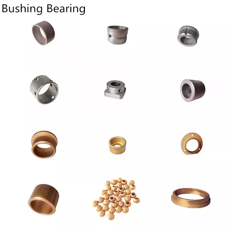
If you are in the market for a casing, there are a few things you should know before buying. First, a bushing is a mechanical part with a rotating or sliding shaft part. You can find them in almost all industrial applications due to their excellent load-carrying capacity and anti-friction properties. They are especially important in construction, mining, agriculture, hydropower, material handling, and more.
bushing

Casing application

The casing market is mainly driven by the growth of the power generation industry. The increasing electrification of Asia Pacific and the deployment of renewable energy in countries such as Saudi Arabia and the UAE are driving the demand for distribution transformer bushings. In addition, the demand for bushings in Western Europe is also likely to increase with the spread of renewable energy and the installation of electric vehicle charging infrastructure. However, the market in Asia Pacific is expected to remain small compared to the rest of the world.
Although bushings are relatively expensive, they are very durable and cost-effective. Furthermore, bushings have a variety of applications, making them an important component in power transformers. For example, power transformers often use bushings to achieve relative movement by sliding or rolling. The vehicle suspension system also uses rubber bushings for a smooth ride and rotating bushings for machine-related operations. They require precision machined parts and are especially useful in applications where high loads and friction must be controlled. Also, plastic bushings are used for wheels in dry kilns, where lubrication is often troublesome.
Transformers require constant monitoring, which is 1 of the reasons bushings are so important in power transformers. Any failure of these components could result in the total loss of the transformer and all surrounding equipment. To maintain high system reliability, utilities must monitor insulation in and around bushings, especially if transformers have been in use for decades. Some utilities have made monitoring the condition of their transformers an important part of their smart grid plans.

Material

The core of the dry casing has many material interfaces. The discharge most likely originates near the edges of the foils and can cause electrical tree growth or breakdown between adjacent foils. Several studies have investigated interfacial effects in composite insulating materials and concluded that the conditions under which the interface occurs is a key factor in determining the growth of electrical trees. This study found that material type and interface conditions are the 2 most important factors for the growth of electrical trees.
Bushings can be made of many different materials, depending on their purpose. The main purpose of the bushing is to support the assembly while protecting it. They must be stiff enough to support the load placed on them, and flexible enough to protect the shaft. Since the shaft is usually not centered on the bushing during rotation, the bushing must be durable enough to carry the load while still protecting the shaft. Here are several materials used for bushings:
A stabilizer bar assembly is a good example of pre-assembly. This pre-assembly enables the vehicle assembly plant to receive components ready for vehicle assembly. The prior art requires the vehicle assembly plant to separate the bushing from the stabilizer bar. However, the present invention eliminates this step and provides a mechanically rigid stabilizer bar assembly. It is designed to prevent audible squeals and improve vehicle performance and handling.
Hardened steel bushings are ideal for pivot and low speed applications. They are made of high carbon steel and fully hardened to 56-62 HRC. Bronze bushings require daily or weekly lubrication but are more expensive than plastic bushings. Plastic bushings are low cost, low maintenance, self lubricating and do not require regular lubrication. These are also suitable for applications with hard to reach parts.
bushing

application

Bushings have many applications in various industries. Most of the time, it is used for drilling. Its excellent chemical and mechanical properties can be used to protect various equipment. These components are versatile and available in a variety of materials. All sleeves are packaged according to national and international standards. They are used in many industrial processes from construction to drilling. Some application examples are listed below.The component 10 may contain a tank for a liquid such as fuel, and the object 12 may be made of fiber reinforced composite material. Sleeve assembly 16 is configured to ground component 10 and object 12 . It may be a bulkhead isolator 40 used to isolate electrical charges in aircraft hydraulic lines. Bushing assembly 16 is 1 of many possible uses for the bushing assembly. The following examples illustrate various applications of bushing assemblies.
Bearings are devices used to reduce friction between moving surfaces. They are a good choice for many applications as they are maintenance free and extend the life of machine components. They can be used in a variety of applications and are often used with plastic and metal materials. For example, Daikin offers bronze and brass bushings. Bushings have many other uses, but they are most commonly used in machines, especially when used in low-load environments.
The most common application for bushings is drilling. Swivel bushings can be used in almost any drilling application. For more complex applications, CZPT's engineering department can create special designs to your specifications. The applications of bushings in machining centers are endless. By providing a smooth, reliable interface, bushings are an excellent choice for precision machining. They can also provide current paths.

Cost

When you have a vehicle that needs a bushing replacement, you may be wondering about the cost of a bushing replacement. The fact is, the cost of a bushing replacement will vary widely, depending on the specific car model. Some cars cost as little as $5, while other vehicles can cost up to $300. The replacement of a control arm bushing may not cost that much, but it's important to know that it's a relatively expensive part to replace.
Most mechanics charge around $375 for a job that involves replacing the bushing in a control arm. However, this price range can vary significantly, depending on whether the mechanic uses OE or aftermarket parts. In any case, the cost of labor is typically included in the price. Some mechanics may even include a labor charge, which is an additional cost. In general, however, the cost of a control arm bushing replacement is comparable to the cost of replacing a single bushing.
Control arm bushings are made of 2 metal cylinders secured together by a thick layer of rubber. Over time, these parts can deteriorate due to accidents, potholes, and off-roading. For this reason, it is important to replace them as soon as possible. Bushing replacement can save you money in the long run, and it's important to have your vehicle repaired as soon as possible. If your control arm bushing is showing signs of wear, you should have it replaced before it becomes completely useless.
If you have decided to replace your suspension bushing yourself, the cost will be considerably lower than you would spend on the replacement of other components. If you have a mechanically-inclined mechanic, you can do it yourself. The parts and labour are reasonably cheap, but the most expensive part is the labor. Because it requires disassembling the wheel and suspension and installing a new bushing, it is important to have a mechanic who has a good understanding of vehicle mechanicry. The cost for control arm bushing replacement is between $20 and $80 per bushing, and a set of 4 costs approximately $300.
bushing

Disambiguation

If you've come across a page containing information about Bushing, you may have been looking for more information. This disambiguation page lists publications about the person, but these have not been assigned to him. We encourage you to contact us if you know who the true author of these publications is. Nevertheless, if you're searching for specific information about Bushing, we recommend you start with CZPT.

China Professional Forage Machinery Omp Hydraulic Motor     with high qualityChina Professional Forage Machinery Omp Hydraulic Motor     with high quality

China Best Sales Percussive Hammers Omp 160 Hydraulic Motor near me supplier

Product Description

Percussive Hammers omp 160 hydraulic motor

Hanjiu specialized in hydrauli orbital motors, our BMP is 100% compatible with OMP

HXIHU (WEST LAKE) DIS.U BMPW of BMPW50,BMPW80,BMPW100,BMPW125,BMPW160,BMPW200,BMPW250,BMPW315,BMPW400 hydraulic wheel motor

1. Compact in design with spool valving motor and geroler

2. Interchangeable with Danfos, CZPT and M+S etc.

3. Widely applicable for machinery like forklifts, lawn mowers, lifts, loaders and excavators etc.

4. Shaft diameter: 25 MM. Thread: 1/2" BSP

5. Very competitive price

6. 1 year of warranty

7. Imported high pressure capacity shaft seal design

8. Design and manufacturing of the spline and drives give the motor durability

9. Wide variety of mounting flanges, shafts,ports and speed provides design flexibility

10. Direction of shaft rotation and speed can be controlled easily and smoothly

11. Best combination of high efficiency and ecnomy in medium duty applications.


Technical Specifications

Part no.

Displace. ml/r

Max. cont. press. bar

Max. cont. 

rpm

Max. cont. torque

N.m

Max. cont. power

Kw

BMPW050

48,6

140

1230

9.3

10.0

BMPW080

77.8

140

770

15.0

10.0

BMPW100

97,3

140

615

19.0

11,0

BMPW125

125.0

140

480

24.0

10.0

BMPW160

155.7

140

385

30.0

10.0

BMPW200

194,6

115

310

30.0

8.0

BMPW250

242,3

90

250

30.0

6.0

BMPW315

306,1

75

195

30.0

5.0

BMPW400

389,2

60

155

30.0

4.0

HXIHU (WEST LAKE) DIS.U TECHNOLOGY , a hydraulic company, has quickly innovated and improved all aspects of its products and services. It is one of the very famous hydraulic motors manufacturers in China, and it already has a good position in the Chinese market. Influenced by the acquisition of Danfos, it is upgrading its industrial chain and expanding its business scope. While improving technology, they also minimize profits, form price and quality advantages, and are committed to developing the most cost-effective hydraulic and other related products in the market, so as to enhance the market competitiveness of hyd motor and strive for good in the international market. reputation and achievements!

If you are a hydraulic importer or distributor, please contact us to discuss cooperation.

How to Calculate Stiffness, Centering Force, Wear and Fatigue Failure of Spline Couplings

There are various types of spline couplings. These couplings have several important properties. These properties are: Stiffness, Involute splines, Misalignment, Wear and fatigue failure. To understand how these characteristics relate to spline couplings, read this article. It will give you the necessary knowledge to determine which type of coupling best suits your needs. Keeping in mind that spline couplings are usually spherical in shape, they are made of steel.
splineshaft

Involute splines

An effective side interference condition minimizes gear misalignment. When 2 splines are coupled with no spline misalignment, the maximum tensile root stress shifts to the left by 5 mm. A linear lead variation, which results from multiple connections along the length of the spline contact, increases the effective clearance or interference by a given percentage. This type of misalignment is undesirable for coupling high-speed equipment.
Involute splines are often used in gearboxes. These splines transmit high torque, and are better able to distribute load among multiple teeth throughout the coupling circumference. The involute profile and lead errors are related to the spacing between spline teeth and keyways. For coupling applications, industry practices use splines with 25 to 50-percent of spline teeth engaged. This load distribution is more uniform than that of conventional single-key couplings.
To determine the optimal tooth engagement for an involved spline coupling, Xiangzhen Xue and colleagues used a computer model to simulate the stress applied to the splines. The results from this study showed that a "permissible" Ruiz parameter should be used in coupling. By predicting the amount of wear and tear on a crowned spline, the researchers could accurately predict how much damage the components will sustain during the coupling process.
There are several ways to determine the optimal pressure angle for an involute spline. Involute splines are commonly measured using a pressure angle of 30 degrees. Similar to gears, involute splines are typically tested through a measurement over pins. This involves inserting specific-sized wires between gear teeth and measuring the distance between them. This method can tell whether the gear has a proper tooth profile.
The spline system shown in Figure 1 illustrates a vibration model. This simulation allows the user to understand how involute splines are used in coupling. The vibration model shows 4 concentrated mass blocks that represent the prime mover, the internal spline, and the load. It is important to note that the meshing deformation function represents the forces acting on these 3 components.
splineshaft

Stiffness of coupling

The calculation of stiffness of a spline coupling involves the measurement of its tooth engagement. In the following, we analyze the stiffness of a spline coupling with various types of teeth using 2 different methods. Direct inversion and blockwise inversion both reduce CPU time for stiffness calculation. However, they require evaluation submatrices. Here, we discuss the differences between these 2 methods.
The analytical model for spline couplings is derived in the second section. In the third section, the calculation process is explained in detail. We then validate this model against the FE method. Finally, we discuss the influence of stiffness nonlinearity on the rotor dynamics. Finally, we discuss the advantages and disadvantages of each method. We present a simple yet effective method for estimating the lateral stiffness of spline couplings.
The numerical calculation of the spline coupling is based on the semi-analytical spline load distribution model. This method involves refined contact grids and updating the compliance matrix at each iteration. Hence, it consumes significant computational time. Further, it is difficult to apply this method to the dynamic analysis of a rotor. This method has its own limitations and should be used only when the spline coupling is fully investigated.
The meshing force is the force generated by a misaligned spline coupling. It is related to the spline thickness and the transmitting torque of the rotor. The meshing force is also related to the dynamic vibration displacement. The result obtained from the meshing force analysis is given in Figures 7, 8, and 9.
The analysis presented in this paper aims to investigate the stiffness of spline couplings with a misaligned spline. Although the results of previous studies were accurate, some issues remained. For example, the misalignment of the spline may cause contact damages. The aim of this article is to investigate the problems associated with misaligned spline couplings and propose an analytical approach for estimating the contact pressure in a spline connection. We also compare our results to those obtained by pure numerical approaches.

Misalignment

To determine the centering force, the effective pressure angle must be known. Using the effective pressure angle, the centering force is calculated based on the maximum axial and radial loads and updated Dudley misalignment factors. The centering force is the maximum axial force that can be transmitted by friction. Several published misalignment factors are also included in the calculation. A new method is presented in this paper that considers the cam effect in the normal force.
In this new method, the stiffness along the spline joint can be integrated to obtain a global stiffness that is applicable to torsional vibration analysis. The stiffness of bearings can also be calculated at given levels of misalignment, allowing for accurate estimation of bearing dimensions. It is advisable to check the stiffness of bearings at all times to ensure that they are properly sized and aligned.
A misalignment in a spline coupling can result in wear or even failure. This is caused by an incorrectly aligned pitch profile. This problem is often overlooked, as the teeth are in contact throughout the involute profile. This causes the load to not be evenly distributed along the contact line. Consequently, it is important to consider the effect of misalignment on the contact force on the teeth of the spline coupling.
The centre of the male spline in Figure 2 is superposed on the female spline. The alignment meshing distances are also identical. Hence, the meshing force curves will change according to the dynamic vibration displacement. It is necessary to know the parameters of a spline coupling before implementing it. In this paper, the model for misalignment is presented for spline couplings and the related parameters.
Using a self-made spline coupling test rig, the effects of misalignment on a spline coupling are studied. In contrast to the typical spline coupling, misalignment in a spline coupling causes fretting wear at a specific position on the tooth surface. This is a leading cause of failure in these types of couplings.
splineshaft

Wear and fatigue failure

The failure of a spline coupling due to wear and fatigue is determined by the first occurrence of tooth wear and shaft misalignment. Standard design methods do not account for wear damage and assess the fatigue life with big approximations. Experimental investigations have been conducted to assess wear and fatigue damage in spline couplings. The tests were conducted on a dedicated test rig and special device connected to a standard fatigue machine. The working parameters such as torque, misalignment angle, and axial distance have been varied in order to measure fatigue damage. Over dimensioning has also been assessed.
During fatigue and wear, mechanical sliding takes place between the external and internal splines and results in catastrophic failure. The lack of literature on the wear and fatigue of spline couplings in aero-engines may be due to the lack of data on the coupling's application. Wear and fatigue failure in splines depends on a number of factors, including the material pair, geometry, and lubrication conditions.
The analysis of spline couplings shows that over-dimensioning is common and leads to different damages in the system. Some of the major damages are wear, fretting, corrosion, and teeth fatigue. Noise problems have also been observed in industrial settings. However, it is difficult to evaluate the contact behavior of spline couplings, and numerical simulations are often hampered by the use of specific codes and the boundary element method.
The failure of a spline gear coupling was caused by fatigue, and the fracture initiated at the bottom corner radius of the keyway. The keyway and splines had been overloaded beyond their yield strength, and significant yielding was observed in the spline gear teeth. A fracture ring of non-standard alloy steel exhibited a sharp corner radius, which was a significant stress raiser.
Several components were studied to determine their life span. These components include the spline shaft, the sealing bolt, and the graphite ring. Each of these components has its own set of design parameters. However, there are similarities in the distributions of these components. Wear and fatigue failure of spline couplings can be attributed to a combination of the 3 factors. A failure mode is often defined as a non-linear distribution of stresses and strains.

China Best Sales Percussive Hammers Omp 160 Hydraulic Motor     near me supplier China Best Sales Percussive Hammers Omp 160 Hydraulic Motor     near me supplier

China wholesaler BMS 2000 / 2K Series Geroler Hydraulic Motor for Crane / Drilling Machines with Great quality

Product Description

BMS 2000 / 2K Series Geroler Hydraulic Motor For Crane / Drilling Machines

Hanjiu BMS= OMS=Eaton 2000 series=M+S MS

BMS hydraulic motor is 1 type of high torque Iow speed hydraulic motors, with high efficiency and long life. BM motor has a wide Speed range, high starting torque and rotating stable at high speed Compact and light, it can be connected to working machine directly, adapted to all kinds of Iow speed heavy load facilities.


Description:


BMS hydraulic motors can well replace OMS series motors from and 2K series motors from EATON.

The Options of BMS-OMS 2K series hydraulic motors: 


- Model - Disc valve, roll-gerotor;


- Flange and wheel mount;


- Shafts - straight, splined and tapered;


- Metric/UNC and BSPP ports;


-Side and rear ports


- Color-Blue, grey ,black ,yellow ;


Features:
 
1. Advanced design in disc distribution flow, which can provide improved performance at low speed.

2. The output shaft adapts in tapered roller bearings that permit high axial and radial forces. Can offer capacities of high pressure and high torque in the wide of applications.

3. Double-rolling bearing design, which permit higher radial loads.


4. Avariety of connection types of flange, output shaft and oil port.
 

Applications:
 

BMS hydraulic motors are widely applied in agriculture machinery, fishing machinery, plastic industry, mining, and construction machinery.

1. Agricultural: all combine harvesters, seeders, rotary tiller, mower, sprayer, feed mixers, ground drilling machine.

2. fishing with: hauling machine.

3. lndustry: winding machines, textile machines, printing presses, operating with a washing machine.

4. construction industry: rollers, cement mixers, cleaning cars.


Product features:
 

Type BMS
BMSE
80
BMS
BMSE
100
BMS
BMSE
125
BMS
BMSE
160
BMS
BMSE
200
BMS
BMSE
250
BMS
BMSE
315
BMS
BMSE
375
Geometric displacement
(cm3 /rev.)
80.6 100.8 125 157.2 200 252 314.5 370
Max. speed (rpm) cont. 800 748 600 470 375 300 240 200
int. 988 900 720 560 450 360 280 240
Max. torque (N·m) cont. 190 240 310 316 400 450 560 536
int. 240 300 370 430 466 540 658 645
peak 260 320 400 472 650 690 740 751
Max. output (kW) cont. 15.9 18.8 19.5 15.6 15.7 14.1 14.1 11.8
int. 20.1 23.5 23.2 21.2 18.3 17 18.9 17
Max. pressure drop (MPa) cont. 17.5 17.5 17.5 15 14 12.5 12 10
int. 21 21 21 21 16 16 14 12
peak 22.5 22.5 22.5 22.5 22.5 20 18.5 14
Max. flow (L/min) cont. 65 75 75 75 75 75 75 75
int. 80 90 90 90 90 90 90 90
Max. inlet pressure (MPa) cont. 25 25 25 25 25 25 25 25
int. 30 30 30 30 30 30 30 30
Weight (kg) 9.8 10 10.3 10.7 11.1 11.6 12.3 12.6

* Continuous pressure :Max. value of operating motor continuously.
* Intermittent pressure :Max. value of operating motor in 6 seconds per minute.
* CZPT pressure:Max. value of operating motor in 0.6 second per minute


Model Crossing:


HXIHU (WEST LAKE) DIS.U
HYDRAULIC
M+S
HYDRAULIC
EATON
CHAR LYNN
  ROSS
TRW
WHITE
CROSS
PARKER SAM
BREVINI
BOSCH
RECROTH
BMM MM MLHK J SERIES OMM       BGM MGX
BMP/BM1 MP HP H SERIES OMP DH MF MG WP RS TC TE TB BG MGP GXP
BMR/BM2 MR HR MLHRW,RW S,T SERIES W SERIES OMR DS OMEW MB WR RE TF BR MGR GMR
BMH/BM4 MH MLHH HW HWF   OMH ME RE TG    
BMS/BM5 MS MSY MLHS 2000 SERIES OMS ME RE TG HPR MGS GMS
BMT/BM6 MT MLHT MTM 6000 SERIES OMT TMT MJ     HT MGT,GMT
BMV MV MLHV 10000 SERIES OMV         MGV GMV


What benefit can i get?


If you are doing hydrualic business, you ae distributing hydraulic components, you can take this motor, add this motor into your catagories, this motor will help you to enlarge your market, If you sell $1,000,000.00 a year, you raise profit by at least 30%, that is $300,000.00.

  • Hanjiu BMS-160-F6-F-S = CZPT Char lynn 2k series, from USA
  • Hanjiu BMS-160-F6-F-S = OMS series, from Danmark
  • Hanjiu BMS-160-F6-F-S = M+S MS series, from Bulgaria
  • we have strong ability to match OEM part no. and provide you.

APPLICATIONS:

  •  Agricultural planting,  
  •  Ground care, Sweeping and Mowing machinery,
  •  Construction,
  •  Forestry, 
  •  wood processing and cutting, 
  •  Farmland irrigation winch ,
  •  Winch Wood from deforestation, 
  •  Construction machinery and platform,
  •  Pilling machines, 
  •  Oceanographic research winch,
  •  Nautical equipment and winches for fishing boats, 
  •  Towing and mooring winches, and many more.


How to work with US

  • discuss your demand with us first
  • we help you to confirm the products
  • match with our models
  • discuss your demand quantity with us, this will help us to provide you our best offer
  • we make a deal on the offer
  • sign a contract
  • you pay deposit
  • we produce
  • you pay balance payment after order ready for shipping
  • dispatch order
  • Payment terms: 30% deposit, 70% balance should be paid before shipping
  • Shipping: by sea, by air, by train
  • Terms: FOB, CFR, CIF
  • Loading port: ZheJiang , HangZhou, ZheJiang , HangZhou, China


Our company:


Elephant Fluid Power has been engaged in the hydraulic business since the beginning of the 20th century. It has a history of nearly 20 years and has always been upholding the principles of "quality first", "credit first" and "zero complaint", and has become a new leader in the hydraulics industry. CZPT Fluid Power insists on good products, good service, and has been providing customers with better, more comprehensive hydraulic products, and constantly.


We are looking for good long business partner and friendship.


If you are interested in our products, please contact me, I will provide the best price support and quality service.
I believe we will establish a good and long-term cooperation.


Helical, Straight-Cut, and Spiral-Bevel Gears

If you are planning to use bevel gears in your machine, you need to understand the differences between Helical, Straight-cut, and Spiral bevel gears. This article will introduce you to these gears, as well as their applications. The article will also discuss the benefits and disadvantages of each type of bevel gear. Once you know the differences, you can choose the right gear for your machine. It is easy to learn about spiral bevel gears.
gear

Spiral bevel gear

Spiral bevel gears play a critical role in the aeronautical transmission system. Their failure can cause devastating accidents. Therefore, accurate detection and fault analysis are necessary for maximizing gear system efficiency. This article will discuss the role of computer aided tooth contact analysis in fault detection and meshing pinion position errors. You can use this method to detect problems in spiral bevel gears. Further, you will learn about its application in other transmission systems.
Spiral bevel gears are designed to mesh the gear teeth more slowly and appropriately. Compared to straight bevel gears, spiral bevel gears are less expensive to manufacture with CNC machining. Spiral bevel gears have a wide range of applications and can even be used to reduce the size of drive shafts and bearings. There are many advantages to spiral bevel gears, but most of them are low-cost.
This type of bevel gear has 3 basic elements: the pinion-gear pair, the load machine, and the output shaft. Each of these is in torsion. Torsional stiffness accounts for the elasticity of the system. Spiral bevel gears are ideal for applications requiring tight backlash monitoring and high-speed operations. CZPT precision machining and adjustable locknuts reduce backlash and allow for precise adjustments. This reduces maintenance and maximizes drive lifespan.
Spiral bevel gears are useful for both high-speed and low-speed applications. High-speed applications require spiral bevel gears for maximum efficiency and speed. They are also ideal for high-speed and high torque, as they can reduce rpm without affecting the vehicle's speed. They are also great for transferring power between 2 shafts. Spiral bevel gears are widely used in automotive gears, construction equipment, and a variety of industrial applications.

Hypoid bevel gear

The Hypoid bevel gear is similar to the spiral bevel gear but differs in the shape of the teeth and pinion. The smallest ratio would result in the lowest gear reduction. A Hypoid bevel gear is very durable and efficient. It can be used in confined spaces and weighs less than an equivalent cylindrical gear. It is also a popular choice for high-torque applications. The Hypoid bevel gear is a good choice for applications requiring a high level of speed and torque.
The Hypoid bevel gear has multiple teeth that mesh with each other at the same time. Because of this, the gear transmits torque with very little noise. This allows it to transfer a higher torque with less noise. However, it must be noted that a Hypoid bevel gear is usually more expensive than a spiral bevel gear. The cost of a Hypoid bevel gear is higher, but its benefits make it a popular choice for some applications.
A Hypoid bevel gear can be made of several types. They may differ in the number of teeth and their spiral angles. In general, the smaller hypoid gear has a larger pinion than its counterpart. This means that the hypoid gear is more efficient and stronger than its bevel cousin. It can even be nearly silent if it is well lubricated. Once you've made the decision to get a Hypoid bevel gear, be sure to read up on its benefits.
Another common application for a Hypoid bevel gear is in automobiles. These gears are commonly used in the differential in automobiles and trucks. The torque transfer characteristics of the Hypoid gear system make it an excellent choice for many applications. In addition to maximizing efficiency, Hypoid gears also provide smoothness and efficiency. While some people may argue that a spiral bevel gear set is better, this is not an ideal solution for most automobile assemblies.
gear

Helical bevel gear

Compared to helical worm gears, helical bevel gears have a small, compact housing and are structurally optimized. They can be mounted in various ways and feature double chamber shaft seals. In addition, the diameter of the shaft and flange of a helical bevel gear is comparable to that of a worm gear. The gear box of a helical bevel gear unit can be as small as 1.6 inches, or as large as 8 cubic feet.
The main characteristic of helical bevel gears is that the teeth on the driver gear are twisted to the left and the helical arc gears have a similar design. In addition to the backlash, the teeth of bevel gears are twisted in a clockwise and counterclockwise direction, depending on the number of helical bevels in the bevel. It is important to note that the tooth contact of a helical bevel gear will be reduced by about 10 to 20 percent if there is no offset between the 2 gears.
In order to create a helical bevel gear, you need to first define the gear and shaft geometry. Once the geometry has been defined, you can proceed to add bosses and perforations. Then, specify the X-Y plane for both the gear and the shaft. Then, the cross section of the gear will be the basis for the solid created after revolution around the X-axis. This way, you can make sure that your gear will be compatible with the pinion.
The development of CNC machines and additive manufacturing processes has greatly simplified the manufacturing process for helical bevel gears. Today, it is possible to design an unlimited number of bevel gear geometry using high-tech machinery. By utilizing the kinematics of a CNC machine center, you can create an unlimited number of gears with the perfect geometry. In the process, you can make both helical bevel gears and spiral bevel gears.

Straight-cut bevel gear

A straight-cut bevel gear is the easiest to manufacture. The first method of manufacturing a straight bevel gear was to use a planer with an indexing head. Later, more efficient methods of manufacturing straight bevel gears were introduced, such as the Revacycle system and the Coniflex system. The latter method is used by CZPT. Here are some of the main benefits of using a straight-cut bevel gear.
A straight-cut bevel gear is defined by its teeth that intersect at the axis of the gear when extended. Straight-cut bevel gears are usually tapered in thickness, with the outer part being larger than the inner portion. Straight-cut bevel gears exhibit instantaneous lines of contact, and are best suited for low-speed, static-load applications. A common application for straight-cut bevel gears is in the differential systems of automobiles.
After being machined, straight-cut bevel gears undergo heat treatment. Case carburizing produces gears with surfaces of 60-63 Rc. Using this method, the pinion is 3 Rc harder than the gear to equalize wear. Flare hardening, flame hardening, and induction hardening methods are rarely used. Finish machining includes turning the outer and inner diameters and special machining processes.
The teeth of a straight-cut bevel gear experience impact and shock loading. Because the teeth of both gears come into contact abruptly, this leads to excessive noise and vibration. The latter limits the speed and power transmission capacity of the gear. On the other hand, a spiral-cut bevel gear experiences gradual but less-destructive loading. It can be used for high-speed applications, but it should be noted that a spiral-cut bevel gear is more complicated to manufacture.
gear

Spur-cut bevel gear

CZPT stocks bevel gears in spiral and straight tooth configurations, in a range of ratios from 1.5 to five. They are also highly remachinable except for the teeth. Spiral bevel gears have a low helix angle and excellent precision properties. CZPT stock bevel gears are manufactured using state-of-the-art technologies and know-how. Compared with spur-cut gears, these have a longer life span.
To determine the strength and durability of a spur-cut bevel gear, you can calculate its MA (mechanical advantage), surface durability (SD), and tooth number (Nb). These values will vary depending on the design and application environment. You can consult the corresponding guides, white papers, and technical specifications to find the best gear for your needs. In addition, CZPT offers a Supplier Discovery Platform that allows you to discover more than 500,000 suppliers.
Another type of spur gear is the double helical gear. It has both left-hand and right-hand helical teeth. This design balances thrust forces and provides extra gear shear area. Helical gears, on the other hand, feature spiral-cut teeth. While both types of gears may generate significant noise and vibration, helical gears are more efficient for high-speed applications. Spur-cut bevel gears may also cause similar effects.
In addition to diametral pitch, the addendum and dedendum have other important properties. The dedendum is the depth of the teeth below the pitch circle. This diameter is the key to determining the center distance between 2 spur gears. The radius of each pitch circle is equal to the entire depth of the spur gear. Spur gears often use the addendum and dedendum angles to describe the teeth.

China wholesaler BMS 2000 / 2K Series Geroler Hydraulic Motor for Crane / Drilling Machines     with Great qualityChina wholesaler BMS 2000 / 2K Series Geroler Hydraulic Motor for Crane / Drilling Machines     with Great quality

China manufacturer Hmgf36fa Fmge49AA Zx300 Ex300-3 Pump Excavator Hydraulic Swing Motor Spare Parts with CZPT with Hot selling

Product Description

Tosion company can perfect interchanged with rexroth/komatsu/hitachi/caterpillar/kayaba/liebherr/messori/toshiba/kawasaki/jeil/teijin seike/uchida/danfoss/linde/eaton/yuken/hawa/parker/nachi/dakin/tokiwa/sam/oilgear etc for all kinds of pump.travel motors&swing motors


REXROTH CAT MESSORI TADANO and other
REXROTH-UCHIDA HITACHI JIC PARKER
SAUER DANFOSS KOMATSU KOBELCO/KATO YUKEN
EATON-VICKERS LINDE JEIL HARVESTER
KAWASAKI KYB TEIJIN Daikin
KAWASAKI SWING MOTOR NACHI TOKIWA ITALY SAM
LIEBHERR TOSHIBA HAWE OILGEAR

Tosion company can perfect interchanged with rexroth/komatsu/hitachi/caterpillar/kayaba/liebherr/messori/toshiba/kawasaki/jeil/teijin seike/uchida/danfoss/linde/eaton/yuken/hawa/parker/nachi/dakin/tokiwa/sam/oilgear etc for all kinds of pump.travel motors&swing motors
Tosion company can perfect interchanged w


The Different Types of Splines in a Splined Shaft

A splined shaft is a machine component with internal and external splines. The splines are formed in 4 different ways: Involute, Parallel, Serrated, and Ball. You can learn more about each type of spline in this article. When choosing a splined shaft, be sure to choose the right 1 for your application. Read on to learn about the different types of splines and how they affect the shaft's performance.
splineshaft

Involute splines

Involute splines in a splined shaft are used to secure and extend mechanical assemblies. They are smooth, inwardly curving grooves that resist separation during operation. A shaft with involute splines is often longer than the shaft itself. This feature allows for more axial movement. This is beneficial for many applications, especially in a gearbox.
The involute spline is a shaped spline, similar to a parallel spline. It is angled and consists of teeth that create a spiral pattern that enables linear and rotatory motion. It is distinguished from other splines by the serrations on its flanks. It also has a flat top. It is a good option for couplers and other applications where angular movement is necessary.
Involute splines are also called involute teeth because of their shape. They are flat on the top and curved on the sides. These teeth can be either internal or external. As a result, involute splines provide greater surface contact, which helps reduce stress and fatigue. Regardless of the shape, involute splines are generally easy to machine and fit.
Involute splines are a type of splines that are used in splined shafts. These splines have different names, depending on their diameters. An example set of designations is for a 32-tooth male spline, a 2,500-tooth module, and a 30 degree pressure angle. An example of a female spline, a fillet root spline, is used to describe the diameter of the splined shaft.
The effective tooth thickness of splines is dependent on the number of keyways and the type of spline. Involute splines in splined shafts should be designed to engage 25 to 50 percent of the spline teeth during the coupling. Involute splines should be able to withstand the load without cracking.

Parallel splines

Parallel splines are formed on a splined shaft by putting 1 or more teeth into another. The male spline is positioned at the center of the female spline. The teeth of the male spline are also parallel to the shaft axis, but a common misalignment causes the splines to roll and tilt. This is common in many industrial applications, and there are a number of ways to improve the performance of splines.
Typically, parallel splines are used to reduce friction in a rotating part. The splines on a splined shaft are narrower on the end face than the interior, which makes them more prone to wear. This type of spline is used in a variety of industries, such as machinery, and it also allows for greater efficiency when transmitting torque.
Involute splines on a splined shaft are the most common. They have equally spaced teeth, and are therefore less likely to crack due to fatigue. They also tend to be easy to cut and fit. However, they are not the best type of spline. It is important to understand the difference between parallel and involute splines before deciding on which spline to use.
The difference between splined and involute splines is the size of the grooves. Involute splines are generally larger than parallel splines. These types of splines provide more torque to the gear teeth and reduce stress during operation. They are also more durable and have a longer life span. And because they are used on farm machinery, they are essential in this type of application.
splineshaft

Serrated splines

A Serrated Splined Shaft has several advantages. This type of shaft is highly adjustable. Its large number of teeth allows large torques, and its shorter tooth width allows for greater adjustment. These features make this type of shaft an ideal choice for applications where accuracy is critical. Listed below are some of the benefits of this type of shaft. These benefits are just a few of the advantages. Learn more about this type of shaft.
The process of hobbing is inexpensive and highly accurate. It is useful for external spline shafts, but is not suitable for internal splines. This type of process forms synchronized shapes on the shaft, reducing the manufacturing cycle and stabilizing the relative phase between spline and thread. It uses a grinding wheel to shape the shaft. CZPT Manufacturing has a large inventory of Serrated Splined Shafts.
The teeth of a Serrated Splined Shaft are designed to engage with the hub over the entire circumference of the shaft. The teeth of the shaft are spaced uniformly around the spline, creating a multiple-tooth point of contact over the entire length of the shaft. The results of these analyses are usually satisfactory. But there are some limitations. To begin with, the splines of the Serrated Splined Shaft should be chosen carefully. If the application requires large-scale analysis, it may be necessary to modify the design.
The splines of the Serrated Splined Shaft are also used for other purposes. They can be used to transmit torque to another device. They also act as an anti-rotational device and function as a linear guide. Both the design and the type of splines determine the function of the Splined Shaft. In the automobile industry, they are used in vehicles, aerospace, earth-moving machinery, and many other industries.

Ball splines

The invention relates to a ball-spinned shaft. The shaft comprises a plurality of balls that are arranged in a series and are operatively coupled to a load path section. The balls are capable of rolling endlessly along the path. This invention also relates to a ball bearing. Here, a ball bearing is 1 of the many types of gears. The following discussion describes the features of a ball bearing.
A ball-splined shaft assembly comprises a shaft with at least 1 ball-spline groove and a plurality of circumferential step grooves. The shaft is held in a first holding means that extends longitudinally and is rotatably held by a second holding means. Both the shaft and the first holding means are driven relative to 1 another by a first driving means. It is possible to manufacture a ball-splined shaft in a variety of ways.
A ball-splined shaft features a nut with recirculating balls. The ball-splined nut rides in these grooves to provide linear motion while preventing rotation. A splined shaft with a nut that has recirculating balls can also provide rotary motion. A ball splined shaft also has higher load capacities than a ball bushing. For these reasons, ball splines are an excellent choice for many applications.
In this invention, a pair of ball-spinned shafts are housed in a box under a carrier device 40. Each of the 2 shafts extends along a longitudinal line of arm 50. One end of each shaft is supported rotatably by a slide block 56. The slide block also has a support arm 58 that supports the center arm 50 in a cantilever fashion.
splineshaft

Sector no-go gage

A no-go gauge is a tool that checks the splined shaft for oversize. It is an effective way to determine the oversize condition of a splined shaft without removing the shaft. It measures external splines and serrations. The no-go gage is available in sizes ranging from 19mm to 130mm with a 25mm profile length.
The sector no-go gage has 2 groups of diametrally opposed teeth. The space between them is manufactured to a maximum space width and the tooth thickness must be within a predetermined tolerance. This gage would be out of tolerance if the splines were measured with a pin. The dimensions of this splined shaft can be found in the respective ANSI or DIN standards.
The go-no-go gage is useful for final inspection of thread pitch diameter. It is also useful for splined shafts and threaded nuts. The thread of a screw must match the contour of the go-no-go gage head to avoid a no-go condition. There is no substitute for a quality machine. It is an essential tool for any splined shaft and fastener manufacturer.
The NO-GO gage can detect changes in tooth thickness. It can be calibrated under ISO17025 standards and has many advantages over a non-go gage. It also gives a visual reference of the thickness of a splined shaft. When the teeth match, the shaft is considered ready for installation. It is a critical process. In some cases, it is impossible to determine the precise length of the shaft spline.
The 45-degree pressure angle is most commonly used for axles and torque-delivering members. This pressure angle is the most economical in terms of tool life, but the splines will not roll neatly like a 30 degree angle. The 45-degree spline is more likely to fall off larger than the other two. Oftentimes, it will also have a crowned look. The 37.5 degree pressure angle is a compromise between the other 2 pressure angles. It is often used when the splined shaft material is harder than usual.

China manufacturer Hmgf36fa Fmge49AA Zx300 Ex300-3 Pump Excavator Hydraulic Swing Motor Spare Parts with CZPT     with Hot sellingChina manufacturer Hmgf36fa Fmge49AA Zx300 Ex300-3 Pump Excavator Hydraulic Swing Motor Spare Parts with CZPT     with Hot selling

China Hot selling Hydraulic Motor Omsy 80 Orbit Motor Replace Char Lynn 2000 104-1022-006 Motor with Great quality

Product Description

 OMSY orbital hydraulic motor

   
OMSY series hydraulic motors are widely applied in agriculture machinery, fishing machinery, plastic industry, mining, and construction machinery.

Code Comparison: 
Danfoss :OMM/ OMP/ OMR/ OMH/ OMS/ OMT/ OMV/ DH/ DS series hydraulic motor.
Eaton : J (129-) series, H(101-) series,S(103-) series,T(158-)series,2000(104-) series,6000 series orbit motor 
M6
  Website:blince


Calculate the ideal mechanical advantage of pulleys

The basic equations for pulleys can be found in this article. It will also cover the different types of pulleys, the ideal mechanical advantages of pulleys, and some common uses of pulley systems. Read on to learn more! After all, a pulley is a simple mechanical device that changes the direction of a force. Learn more about pulleys and their common uses in engineering.
pulley

pulley basic equation

Pulleys work the same way as gravity, so they should withstand similar forces. Newton's laws of motion can be used to calculate the forces in a pulley system. The second law of motion applies to forces and accelerations. Similar to this is Newton's third law, which states that the directions of forces are equal and opposite. The fourth law dictates the direction of force. The Fifth Law states that tension is in equilibrium with gravity.
A pulley is a simple mechanism that transmits force by changing direction. They are generally considered to have negligible mass and friction, but this is only an approximation. Pulleys have different uses, from sailboats to farms and large construction cranes. In fact, they are the most versatile mechanisms in any system. Some of their most common applications and equations are listed below.
For example, consider 2 masses m. Those of mass m will be connected by pulleys. The static friction coefficient of the left stop is ms1, and the static friction coefficient of the right stop is ms2. A no-slip equation will contain multiple inequalities. If the 2 blocks are considered to be connected by a pulley, the coefficient of kinetic friction is mk. In other words, the weight of each block carries the same mass, but in the opposite direction.

Types of pulleys

A pulley is a device used to pull and push objects. Pulley systems are ropes, cables, belts or chains. The "drive pulley" is attached to the shaft and moves the driven pulley. They are available in a variety of sizes, and the larger they are, the higher the speed of power transmission. Alternatively, use small pulleys for smaller applications.
Two-wheel pulleys have 2 mechanical advantages. The greater the mechanical advantage, the less force is required to move the object. More wheels lift more weight, but smaller pulleys require less force. In a two-wheel pulley system, the rope is wound around 2 axles and a fixed surface. As you pull on the rope, the shafts above slowly come together.
Compound pulleys have 2 or more rope segments that are pulled up on the load. The mechanical advantage of compound pulleys depends on the number of rope segments and how they are arranged. This type of pulley can increase the force by changing the direction of the rope segment. There are 2 main types of pulleys. Composite pulleys are most commonly used in construction. The ideal mechanical advantage of pulleys is 2 or more.
Construction pulleys are a basic type. They are usually attached to wheel rails and can be lifted to great heights. Combinations of axes are also common. Construction pulleys can be raised to great heights to access materials or equipment. When used in construction, these pulleys are usually made of heavy materials such as wood or metal. They are secured with ropes or chains.

The ideal mechanical advantage of pulleys

The pulley system is a highly complex system with high mechanical advantages. Use a single pulley system to reduce the force required to lift an object by cutting it in half. The mechanical advantage increases as you add more pulleys, such as 6 or seven. To calculate the mechanical advantage of a pulley system, you need to count the number of rope segments between the pulleys. If the free end of the rope is facing down, don't count it. If it's facing up, count. Once you have your number, add it up.
The required mechanical advantage of a pulley is the number of rope segments it has to pull the load. The more rope segments, the lower the force. Therefore, the more rope segments the pulley has, the lower the force. If the rope segments are four, then the ideal mechanical advantage is four. In this case, the composite pulley quadrupled the load force.
The ideal mechanical advantage of a pulley system is the sum of the mechanical force and the force required to lift the load at its output. Typically, a single pulley system uses 2 ropes, and the mechanical force required to lift the load is multiplied by the 2 ropes. For a multi-pulley system, the number of ropes will vary, but the total energy requirement will remain the same. The friction between the rope and pulley increases the force and energy required to lift the load, so the mechanical advantage diminishes over time.
pulley

Common uses of pulley systems

A pulley system is a simple mechanical device typically used to lift heavy objects. It consists of a rotating wheel attached to a fixed shaft and a rope attached to it. When the wheel moves, the force applied by the operator is multiplied by the speed of the pulley, and the force is multiplied by the weight of the object being lifted. Common uses for pulley systems include pulling, lifting, and moving heavy objects.
The oil and petroleum industries use pulley systems in a variety of applications. Most commonly, pulleys are used in drilling operations and they are installed on top of the rig to guide the cable. The cable itself is attached to 2 pulleys suspended in the derrick, where they provide mechanical energy to the cable. Using a pulley system in this application provides the force needed to move the cable safely and smoothly.
The main advantage of the pulley system is that it minimizes the force required to lift an object. The force used to lift the object is multiplied by the desired mechanical advantage. The more rope segments, the lower the force required. On the other hand, a compound pulley system can have many segments. Therefore, a compound pulley system can increase the force a worker can exert on an object.
Safety Precautions to Take When Working on Pulley Systems

There are many safety precautions that should be observed when working on a pulley system. The first is to wear proper protective gear. This includes hard hats that protect you from falling objects. Also, gloves may be required. You should limit the amount of movement in the penalty area, and you should also keep the area free of unnecessary people and objects. Also, remember to wear a hard hat when working on the pulley system.
Another important safety precaution when working on a pulley system is to check the Safe Working Load (SWL) of the pulley before attaching anything. This will help you understand the maximum weight the pulley can hold. Also, consider the angle and height of the pulley system. Always use safety anchors and always remember to wear a hat when working on a pulley system.
Safe use of chain hoists requires training and experience. It is important to read the manufacturer's manual and follow all safety precautions. If you're not sure, you can actually inspect the hoist and look for signs of damage or tampering. Look for certifications for sprocket sets and other lifting accessories. Look for the Safe Working Load (SWL) marking on the chain hoist.
pulley

Example of a pulley system

Pulley systems are often used to lift items. It allows you to reduce the effort to lift and move the load by applying force in 1 direction. Pulley systems can be built and modeled to fit any type of project. This resource focuses on pulley systems and is designed to support the new GCSEs in Engineering, Design and Technology. There are also many examples of pulley systems suitable for various applications.
In the study, participants who read easy text took longer to manipulate the pulley system than those who read challenging text. In general, this suggests that participants with prior scientific experience used their cognitive abilities more effectively. Additionally, students who read simple texts spent less time planning the pulley system and more time on other tasks. However, the study did show that the time required to plan the pulley system was similar between the 2 groups.
In everyday life, pulley systems are used to lift various objects. Flagpoles are 1 of many pulley systems used to raise and lower flagpoles. They can also be used to raise and lower garage doors. Likewise, rock climbers use pulleys to help them ascend and descend. The pulley system can also be used to extend the ladder.

China Hot selling Hydraulic Motor Omsy 80 Orbit Motor Replace Char Lynn 2000 104-1022-006 Motor     with Great qualityChina Hot selling Hydraulic Motor Omsy 80 Orbit Motor Replace Char Lynn 2000 104-1022-006 Motor     with Great quality

China best Hydraulic Components Danfos Omp Motor with Good quality

Product Description

Hydraulic Components danfos omp motor

Hanjiu specialized in hydrauli orbital motors, our BMP is 100% compatible with OMP

HXIHU (WEST LAKE) DIS.U BMPW of BMPW50,BMPW80,BMPW100,BMPW125,BMPW160,BMPW200,BMPW250,BMPW315,BMPW400 hydraulic wheel motor

1. Compact in design with spool valving motor and geroler

2. Interchangeable with Danfos, CZPT and M+S etc.

3. Widely applicable for machinery like forklifts, lawn mowers, lifts, loaders and excavators etc.

4. Shaft diameter: 25 MM. Thread: 1/2" BSP

5. Very competitive price

6. 1 year of warranty

7. Imported high pressure capacity shaft seal design

8. Design and manufacturing of the spline and drives give the motor durability

9. Wide variety of mounting flanges, shafts,ports and speed provides design flexibility

10. Direction of shaft rotation and speed can be controlled easily and smoothly

11. Best combination of high efficiency and ecnomy in medium duty applications.


Technical Specifications

Part no.

Displace. ml/r

Max. cont. press. bar

Max. cont. 

rpm

Max. cont. torque

N.m

Max. cont. power

Kw

BMPW050

48,6

140

1230

9.3

10.0

BMPW080

77.8

140

770

15.0

10.0

BMPW100

97,3

140

615

19.0

11,0

BMPW125

125.0

140

480

24.0

10.0

BMPW160

155.7

140

385

30.0

10.0

BMPW200

194,6

115

310

30.0

8.0

BMPW250

242,3

90

250

30.0

6.0

BMPW315

306,1

75

195

30.0

5.0

BMPW400

389,2

60

155

30.0

4.0

HXIHU (WEST LAKE) DIS.U TECHNOLOGY , a hydraulic company, has quickly innovated and improved all aspects of its products and services. It is one of the very famous hydraulic motors manufacturers in China, and it already has a good position in the Chinese market. Influenced by the acquisition of Danfos, it is upgrading its industrial chain and expanding its business scope. While improving technology, they also minimize profits, form price and quality advantages, and are committed to developing the most cost-effective hydraulic and other related products in the market, so as to enhance the market competitiveness of hyd motor and strive for good in the international market. reputation and achievements!

If you are a hydraulic importer or distributor, please contact us to discuss cooperation.

Screw Sizes and Their Uses

Screws have different sizes and features. This article will discuss screw sizes and their uses. There are 2 main types: right-handed and left-handed screw shafts. Each screw features a point that drills into the object. Flat tipped screws, on the other hand, need a pre-drilled hole. These screw sizes are determined by the major and minor diameters. To determine which size of screw you need, measure the diameter of the hole and the screw bolt's thread depth.

The major diameter of a screw shaft

The major diameter of a screw shaft is the distance from the outer edge of the thread on 1 side to the tip of the other. The minor diameter is the inner smooth part of the screw shaft. The major diameter of a screw is typically between 2 and 16 inches. A screw with a pointy tip has a smaller major diameter than 1 without. In addition, a screw with a larger major diameter will have a wider head and drive.
The thread of a screw is usually characterized by its pitch and angle of engagement. The pitch is the angle formed by the helix of a thread, while the crest forms the surface of the thread corresponding to the major diameter of the screw. The pitch angle is the angle between the gear axis and the pitch surface. Screws without self-locking threads have multiple starts, or helical threads.
The pitch is a crucial component of a screw's threading system. Pitch is the distance from a given thread point to the corresponding point of the next thread on the same shaft. The pitch line is 1 element of pitch diameter. The pitch line, or lead, is a crucial dimension for the thread of a screw, as it controls the amount of thread that will advance during a single turn.
screwshaft

The pitch diameter of a screw shaft

When choosing the appropriate screw, it is important to know its pitch diameter and pitch line. The pitch line designates the distance between adjacent thread sides. The pitch diameter is also known as the mean area of the screw shaft. Both of these dimensions are important when choosing the correct screw. A screw with a pitch of 1/8 will have a mechanical advantage of 6.3. For more information, consult an application engineer at Roton.
The pitch diameter of a screw shaft is measured as the distance between the crest and the root of the thread. Threads that are too long or too short will not fit together in an assembly. To measure pitch, use a measuring tool with a metric scale. If the pitch is too small, it will cause the screw to loosen or get stuck. Increasing the pitch will prevent this problem. As a result, screw diameter is critical.
The pitch diameter of a screw shaft is measured from the crest of 1 thread to the corresponding point on the next thread. Measurement is made from 1 thread to another, which is then measured using the pitch. Alternatively, the pitch diameter can be approximated by averaging the major and minor diameters. In most cases, the pitch diameter of a screw shaft is equal to the difference between the two.

The thread depth of a screw shaft

Often referred to as the major diameter, the thread depth is the outermost diameter of the screw. To measure the thread depth of a screw, use a steel rule, micrometer, or caliper. In general, the first number in the thread designation indicates the major diameter of the thread. If a section of the screw is worn, the thread depth will be smaller, and vice versa. Therefore, it is good practice to measure the section of the screw that receives the least amount of use.
In screw manufacturing, the thread depth is measured from the crest of the screw to the root. The pitch diameter is halfway between the major and minor diameters. The lead diameter represents the amount of linear distance traveled in 1 revolution. As the lead increases, the load capacity decreases. This measurement is primarily used in the construction of screws. However, it should not be used for precision machines. The thread depth of a screw shaft is essential for achieving accurate screw installation.
To measure the thread depth of a screw shaft, the manufacturer must first determine how much material the thread is exposed to. If the thread is exposed to side loads, it can cause the nut to wedge. Because the nut will be side loaded, its thread flanks will contact the nut. The less clearance between the nut and the screw, the lower the clearance between the nut and the screw. However, if the thread is centralized, there is no risk of the nut wedgeing.
screwshaft

The lead of a screw shaft

Pitch and lead are 2 measurements of a screw's linear distance per turn. They're often used interchangeably, but their definitions are not the same. The difference between them lies in the axial distance between adjacent threads. For single-start screws, the pitch is equal to the lead, while the lead of a multi-start screw is greater than the pitch. This difference is often referred to as backlash.
There are 2 ways to calculate the pitch and lead of a screw. For single-start screws, the lead and pitch are equal. Multiple-start screws, on the other hand, have multiple starts. The pitch of a multiple-start screw is the same as its lead, but with 2 or more threads running the length of the screw shaft. A square-thread screw is a better choice in applications requiring high load-bearing capacity and minimal friction losses.
The PV curve defines the safe operating limits of lead screw assemblies. It describes the inverse relationship between contact surface pressure and sliding velocity. As the load increases, the lead screw assembly must slow down in order to prevent irreversible damage from frictional heat. Furthermore, a lead screw assembly with a polymer nut must reduce rpm as the load increases. The more speed, the lower the load capacity. But, the PV factor must be below the maximum allowed value of the material used to make the screw shaft.

The thread angle of a screw shaft

The angle between the axes of a thread and the helix of a thread is called the thread angle. A unified thread has a 60-degree angle in all directions. Screws can have either a tapped hole or a captive screw. The screw pitch is measured in millimeters (mm) and is usually equal to the screw major diameter. In most cases, the thread angle will be equal to 60-degrees.
Screws with different angles have various degrees of thread. Originally, this was a problem because of the inconsistency in the threading. However, Sellers's thread was easier to manufacture and was soon adopted as a standard throughout the United States. The United States government began to adopt this thread standard in the mid-1800s, and several influential corporations in the railroad industry endorsed it. The resulting standard is called the United States Standard thread, and it became part of the ASA's Vol. 1 publication.
There are 2 types of screw threads: coarse and fine. The latter is easier to tighten and achieves tension at lower torques. On the other hand, the coarse thread is deeper than the fine one, making it easier to apply torque to the screw. The thread angle of a screw shaft will vary from bolt to bolt, but they will both fit in the same screw. This makes it easier to select the correct screw.
screwshaft

The tapped hole (or nut) into which the screw fits

A screw can be re-threaded without having to replace it altogether. The process is different than that of a standard bolt, because it requires threading and tapping. The size of a screw is typically specified by its major and minor diameters, which is the inside distance between threads. The thread pitch, which is the distance between each thread, is also specified. Thread pitch is often expressed in threads per inch.
Screws and bolts have different thread pitches. A coarse thread has fewer threads per inch and a longer distance between threads. It is therefore larger in diameter and longer than the material it is screwed into. A coarse thread is often designated with an "A" or "B" letter. The latter is generally used in smaller-scale metalworking applications. The class of threading is called a "threaded hole" and is designated by a letter.
A tapped hole is often a complication. There is a wide range of variations between the sizes of threaded holes and nut threads, so the tapped hole is a critical dimension in many applications. However, even if you choose a threaded screw that meets the requisite tolerance, there may be a mismatch in the thread pitch. This can prevent the screw from freely rotating.

China best Hydraulic Components Danfos Omp Motor     with Good qualityChina best Hydraulic Components Danfos Omp Motor     with Good quality

China OEM Excavator Parts GM06 hydraulic Travel Motor Final Drive For PC45 PC50 PC55 PC50UU-2 PC56 PC60 SK55 EX60 SK50 FOB Reference Price with high quality

Situation: New
Applicable Industries: Constructing Substance Retailers, Machinery Fix Shops, Production Plant, Farms, Retail, Development works , Power & Mining
Showroom Area: Canada, United Kingdom, United States, Italy, extended lifespan valve h2o meter custom dimensions pace torque gearbox wholesale planetary equipment motor actuator reducer France, Germany, Brazil, Spain, South Korea, Japan, Australia
Video outgoing-inspection: Offered
Machinery Test Report: Supplied
Marketing and advertising Variety: New Item 2571
Guarantee: 6 Months
Element title: Excavator fittings
Component amount: GM06
Application: Excavator
MOQ: 1pcs
Shipping and delivery: 1-3 Times
OEM: Accpetable
Payment Term: TT.western Union.Paypal.Alipay
Packing: Carton
Packaging Specifics: Cartoon box

Products Description DescriptionSwing MotorOEM No. GM06GuaranteeSix months Shipping Timethree-7 organization daysPackaging Carton boxOther reference No. 4699092Matches DesignsPC45 PC50 PC55 PC50UU-2 PC56 PC60 SK55 EX60 SK50 Firm Profile HangZhou Xihu (West Lake) Dis.ju equipment CO,.Ltd. The company was set up in 2006, previously identified as Xihu (West Lake) Dis.ju OEM spare areas producer, with fifteen a long time of knowledge inmachinery components creation and intercontinental trade. The organization engaged in a complete variety of spare areas of global well-recognized brands-CATERPILLAR, 2141-2215078 Autoparts Push Shaft Joint Kits inner For AZLK 2141 Mosckvich KOMATSU, HITACHI, Shantui, KOBELCO, SANY, XCMG, Doosan, Kubota, VOLVO, CUMMINS, Electric Quad Bike ATV 750w Shaft Push LiuGong, SDLG. Welcome pals to check out from all over the world! Solution packaging and shipping Client Images Certifications FAQ 1. How to ship the items?UPS, DHL, FedEx, EMS, Air Freight and Sea Freight are all good with us.2.Are you manufacturing unit or buying and selling business?We are manufacturing unit and wholesaler of the whole range spare elements of large development machines.3.How can I shell out for the orders?We settle for RMB/USD lender transfer, Western Union, T/T, Paypal and Alibaba trade assurance.4.How can you aid me if the merchandise I receive has high quality problemsWe change them freely during the warranty interval. Why Decide on Us A single-end Store for your busienss Your spare elements specilist Deliver on the working day Legitimate/OEM/ODM quality Aggressive value Powerful overall performance Make contact with Us

How to Change the Travel Shaft

Several different capabilities in a motor vehicle are essential to its functioning, but the driveshaft is possibly the element that demands to be comprehended the most. A damaged or destroyed driveshaft can damage several other vehicle components. This report will make clear how this component works and some of the symptoms that it could require mend. This article is for the common individual who would like to correct their vehicle on their personal but may not be familiar with mechanical repairs or even driveshaft mechanics. You can click the link under for more information.
air-compressor

Restore broken driveshafts

If you own a vehicle, you should know that the driveshaft is an integral element of the vehicle's driveline. They guarantee effective transmission of power from the engine to the wheels and drive. Nevertheless, if your driveshaft is ruined or cracked, your car will not operate properly. To hold your vehicle risk-free and running at peak effectiveness, you should have it fixed as soon as attainable. Below are some straightforward measures to change the travel shaft.
Initial, diagnose the trigger of the drive shaft injury. If your automobile is producing abnormal noises, the driveshaft may be ruined. This is due to the fact worn bushings and bearings assist the generate shaft. For that reason, the rotation of the push shaft is impacted. The sound will be squeaks, dings or rattles. When the difficulty has been diagnosed, it is time to repair the ruined generate shaft.
Pros can restore your driveshaft at relatively lower price. Costs vary dependent on the sort of drive shaft and its problem. Axle repairs can range from $three hundred to $1,000. Labor is normally only close to $two hundred. A easy mend can price among $one hundred fifty and $1700. You are going to save hundreds of bucks if you happen to be capable to resolve the problem yourself. You could require to spend a few far more several hours educating your self about the dilemma prior to handing it more than to a skilled for appropriate diagnosis and repair.
The cost of fixing a destroyed driveshaft varies by product and manufacturer. It can value as much as $2,000 dependent on parts and labor. Even though labor charges can vary, components and labor are generally around $70. On regular, a broken driveshaft mend fees amongst $four hundred and $600. Nonetheless, these areas can be far more costly than that. If you never want to spend money on unnecessarily expensive repairs, you may possibly need to spend a tiny more.
air-compressor

Learn how drive shafts function

While a vehicle motor might be one particular of the most complicated components in your car, the driveshaft has an equally essential job. The driveshaft transmits the energy of the engine to the wheels, turning the wheels and making the vehicle transfer. Driveshaft torque refers to the force linked with rotational movement. Push shafts must be ready to endure extreme circumstances or they might split. Driveshafts are not created to bend, so understanding how they work is vital to the appropriate performing of the vehicle.
The travel shaft contains many elements. The CV connector is a single of them. This is the last end prior to the wheels spin. CV joints are also known as "doughnut" joints. The CV joint assists harmony the load on the driveshaft, the final cease amongst the motor and the final travel assembly. Ultimately, the axle is a single rotating shaft that transmits power from the ultimate drive assembly to the wheels.
Distinct varieties of push shafts have diverse numbers of joints. They transmit torque from the motor to the wheels and should accommodate variations in duration and angle. The push shaft of a front-wheel generate vehicle usually includes a connecting shaft, an internal continual velocity joint and an outer fastened joint. They also have anti-lock program rings and torsional dampers to support them operate efficiently. This manual will support you recognize the fundamentals of driveshafts and keep your auto in great form.
The CV joint is the coronary heart of the driveshaft, it enables the wheels of the car to move at a constant speed. The connector also aids transmit electrical power effectively. You can discover far more about CV joint driveshafts by hunting at the leading 3 driveshaft questions
The U-joint on the intermediate shaft may possibly be worn or ruined. Tiny deviations in these joints can cause slight vibrations and wobble. Over time, these vibrations can use out drivetrain components, which includes U-joints and differential seals. Further dress in on the center assist bearing is also anticipated. If your driveshaft is leaking oil, the next action is to verify your transmission.
The push shaft is an crucial part of the vehicle. They transmit energy from the engine to the transmission. They also hook up the axles and CV joints. When these elements are in very good condition, they transmit energy to the wheels. If you locate them free or caught, it can cause the car to bounce. To guarantee suitable torque transfer, your auto requirements to keep on the road. While tough roads are typical, bumps and bumps are frequent.
air-compressor

Widespread indications of damaged driveshafts

If your motor vehicle vibrates greatly beneath, you might be dealing with a faulty propshaft. This problem boundaries your total control of the car and can not be ignored. If you hear this sound usually, the difficulty might be the trigger and must be identified as quickly as feasible. Right here are some widespread signs of a damaged driveshaft. If you knowledge this sounds even though driving, you need to have your car inspected by a mechanic.
A clanging sound can also be a single of the symptoms of a destroyed driveshaft. A ding may possibly be a indicator of a defective U-joint or center bearing. This can also be a symptom of worn centre bearings. To hold your car protected and working properly, it is ideal to have your driveshaft inspected by a accredited mechanic. This can avoid critical injury to your automobile.
A worn push shaft can cause problems turning, which can be a significant security issue. Fortunately, there are a lot of ways to explain to if your driveshaft wants services. The very first issue you can do is check the u-joint itself. If it moves also significantly or also minor in any path, it probably signifies your driveshaft is faulty. Also, rust on the bearing cap seals may show a defective generate shaft.
The following time your vehicle rattles, it may well be time for a mechanic to verify it out. Whether or not your motor vehicle has a handbook or computerized transmission, the driveshaft performs an critical role in your vehicle's performance. When 1 or both driveshafts fall short, it can make the automobile unsafe or not possible to generate. Consequently, you must have your vehicle inspected by a mechanic as shortly as feasible to avoid additional issues.
Your automobile need to also be frequently lubricated with grease and chain to avert corrosion. This will prevent grease from escaping and causing dirt and grease to develop up. One more widespread signal is a soiled driveshaft. Make sure your telephone is free of particles and in great condition. Lastly, make confident the driveshaft chain and go over are in place. In most cases, if you observe any of these frequent signs, your vehicle's driveshaft ought to be changed.
Other symptoms of a damaged driveshaft consist of uneven wheel rotation, difficulty turning the car, and improved drag when making an attempt to turn. A worn U-joint also inhibits the potential of the steering wheel to turn, generating it a lot more hard to turn. Yet another sign of a defective driveshaft is the shuddering sounds the car helps make when accelerating. Automobiles with ruined driveshafts must be inspected as shortly as attainable to keep away from pricey repairs.

China OEM Excavator Parts GM06 hydraulic Travel Motor Final Drive For PC45 PC50 PC55 PC50UU-2 PC56 PC60 SK55 EX60 SK50 FOB Reference Price  with high high qualityChina OEM Excavator Parts GM06 hydraulic Travel Motor Final Drive For PC45 PC50 PC55 PC50UU-2 PC56 PC60 SK55 EX60 SK50 FOB Reference Cost  with substantial quality