Tag Archives: tractor china

China best Agricultural Machinery Cutting Machine Tractor Light Grass Side Lawn Finishing Flail Mower for Tractor From China Factory with Great quality

Product Description

Product Description


Agricultural Machinery Grass Cutting Machine Tractor Light Grass Side Lawn Flail Lawn Finishing Mower for Tractor:

PRODUCT DETAILS:

1 Transmission: By sturdy toothed belts.(VB Belt)
2 Graphite gearbox is made of casting iron
3 The suspension plate shape is made by laser cutting,molding location
4 With adjustable rear roller, the mowing height can be adjusted easily
5 Side protection plates are added CZPT the rear deflection
6 Y shape blades, hammer and straight blades for grass. (Optional for customers.)
7 The blades are under hot dealing and special testing
8 With front protection, to avoid splashing
9 Use powder painting
10 Labels are:water proof, damp proof, CZPT proof, anti-ultraviolet radiation


Guarantee & Warranty:
 

1 Warranty time:14months,longer than any other Chinese suppliers.
2 With CE CERTIFICATES.
3 All of your ordered machines will be tested to ensure the quality before shipment.
4 We will provide you with the test reports together with the container or sample packages.
5 Even the packages,all of them are guaranteed for customs check or inspections.


Main Products

Why Choose Us

HangZhou BETTER. AGRO Industry (B.T.A), as 1 of the leading manufacturers in the production of agricultural equipments, is located in TiHangZhou District, HangZhou, ZheJiang , China, with good location, convenient transportation and complement resources.

B.T.A's motto is "tending to the details others can 't ", and it is committed to creating the top brand in the high-end agricultural machinery. In line with the philosophy of "taking the initiative to participate in market competition", B.T.A spares no effort to design and develop the most professional and the most sophisticated new types of agricultural machinery products.

B.T.A has professional laser cutting machines, fully automatic CNC bending machines, standard welding jigs and automatic spraying production line and other advanced production equipment, as well as excellent technology research and development team. It strictly follows European & American Design and Use Standard and adopts an advanced management system and strict quality control. It not only gives strict product performance assessment according to the field test specification and passed the CE certification, but also constantly improves and upgrades products after user feedback. B.T.A is well known with its superior design, rich varieties and reliable quality, it is especially recognized in the United States, Germany, Netherlands, Belgium, Australia and other countries.

B.T.A is mainly engaged in the research and development, manufacturing and sales of various types of agricultural and garden machinery. Our main products are divided into our categories: farm machinery, garden machinery, forestry machinery and road machinery. Some of our well known products include 3 point linkage rotary tiller, finishing mower, flail mower, verge flail mower, rotary slasher, wood chipper, trailer, spare parts and Japanese tractor accessories, which are exported to over 20 countries.

In the future, B.T.A will further optimize the structure of existing products according to the requirements and characteristics of farmers, satisfy the needs of the international market and establish the perfect after-sales service system.

Certifications

Process

FAQ

Q1. What are your terms of packing?

A: Generally, we pack our goods in bulks or wooden box, suitable for shipping container.


Q2. What is your terms of payment?

A: T/T 30% as deposit, and 70% before delivery. We'll show you the photos of the products and packages before you pay the balance.


Q3. What are your terms of delivery?

A: EXW, FOB, CFR, CIF.


Q4. How about your delivery time?

A: Generally, it will take 10 to 15 days after receiving your advance payment. The specific delivery time depends 

on the items and the quantity of your order. 


Q5. Can you produce according to the samples?

A: Yes, we can produce by your samples or technical drawings.


Q6. What is your sample policy?

A: We can supply the sample if we have ready parts in stock.


Q7. Do you test all your goods before delivery?

A: Yes, we have 100% test before delivery.


Q8: How do you make our business long-term and good relationship?

A1:We keep excellent quality, thoughtful after-sales service and competitive price to ensure our customers' benefit;

A2:We respect every customer as our friend and we sincerely do business and make friends with them, no matter where they come from

How to Replace the Drive Shaft

Several different functions in a vehicle are critical to its functioning, but the driveshaft is probably the part that needs to be understood the most. A damaged or damaged driveshaft can damage many other auto parts. This article will explain how this component works and some of the signs that it may need repair. This article is for the average person who wants to fix their car on their own but may not be familiar with mechanical repairs or even driveshaft mechanics. You can click the link below for more information.
air-compressor

Repair damaged driveshafts

If you own a car, you should know that the driveshaft is an integral part of the vehicle's driveline. They ensure efficient transmission of power from the engine to the wheels and drive. However, if your driveshaft is damaged or cracked, your vehicle will not function properly. To keep your car safe and running at peak efficiency, you should have it repaired as soon as possible. Here are some simple steps to replace the drive shaft.
First, diagnose the cause of the drive shaft damage. If your car is making unusual noises, the driveshaft may be damaged. This is because worn bushings and bearings support the drive shaft. Therefore, the rotation of the drive shaft is affected. The noise will be squeaks, dings or rattles. Once the problem has been diagnosed, it is time to repair the damaged drive shaft.
Professionals can repair your driveshaft at relatively low cost. Costs vary depending on the type of drive shaft and its condition. Axle repairs can range from $300 to $1,000. Labor is usually only around $200. A simple repair can cost between $150 and $1700. You'll save hundreds of dollars if you're able to fix the problem yourself. You may need to spend a few more hours educating yourself about the problem before handing it over to a professional for proper diagnosis and repair.
The cost of repairing a damaged driveshaft varies by model and manufacturer. It can cost as much as $2,000 depending on parts and labor. While labor costs can vary, parts and labor are typically around $70. On average, a damaged driveshaft repair costs between $400 and $600. However, these parts can be more expensive than that. If you don't want to spend money on unnecessarily expensive repairs, you may need to pay a little more.
air-compressor

Learn how drive shafts work

While a car engine may be 1 of the most complex components in your vehicle, the driveshaft has an equally important job. The driveshaft transmits the power of the engine to the wheels, turning the wheels and making the vehicle move. Driveshaft torque refers to the force associated with rotational motion. Drive shafts must be able to withstand extreme conditions or they may break. Driveshafts are not designed to bend, so understanding how they work is critical to the proper functioning of the vehicle.
The drive shaft includes many components. The CV connector is 1 of them. This is the last stop before the wheels spin. CV joints are also known as "doughnut" joints. The CV joint helps balance the load on the driveshaft, the final stop between the engine and the final drive assembly. Finally, the axle is a single rotating shaft that transmits power from the final drive assembly to the wheels.
Different types of drive shafts have different numbers of joints. They transmit torque from the engine to the wheels and must accommodate differences in length and angle. The drive shaft of a front-wheel drive vehicle usually includes a connecting shaft, an inner constant velocity joint and an outer fixed joint. They also have anti-lock system rings and torsional dampers to help them run smoothly. This guide will help you understand the basics of driveshafts and keep your car in good shape.
The CV joint is the heart of the driveshaft, it enables the wheels of the car to move at a constant speed. The connector also helps transmit power efficiently. You can learn more about CV joint driveshafts by looking at the top 3 driveshaft questions
The U-joint on the intermediate shaft may be worn or damaged. Small deviations in these joints can cause slight vibrations and wobble. Over time, these vibrations can wear out drivetrain components, including U-joints and differential seals. Additional wear on the center support bearing is also expected. If your driveshaft is leaking oil, the next step is to check your transmission.
The drive shaft is an important part of the car. They transmit power from the engine to the transmission. They also connect the axles and CV joints. When these components are in good condition, they transmit power to the wheels. If you find them loose or stuck, it can cause the vehicle to bounce. To ensure proper torque transfer, your car needs to stay on the road. While rough roads are normal, bumps and bumps are common.
air-compressor

Common signs of damaged driveshafts

If your vehicle vibrates heavily underneath, you may be dealing with a faulty propshaft. This issue limits your overall control of the vehicle and cannot be ignored. If you hear this noise frequently, the problem may be the cause and should be diagnosed as soon as possible. Here are some common symptoms of a damaged driveshaft. If you experience this noise while driving, you should have your vehicle inspected by a mechanic.
A clanging sound can also be 1 of the signs of a damaged driveshaft. A ding may be a sign of a faulty U-joint or center bearing. This can also be a symptom of worn center bearings. To keep your vehicle safe and functioning properly, it is best to have your driveshaft inspected by a certified mechanic. This can prevent serious damage to your car.
A worn drive shaft can cause difficulty turning, which can be a major safety issue. Fortunately, there are many ways to tell if your driveshaft needs service. The first thing you can do is check the u-joint itself. If it moves too much or too little in any direction, it probably means your driveshaft is faulty. Also, rust on the bearing cap seals may indicate a faulty drive shaft.
The next time your car rattles, it might be time for a mechanic to check it out. Whether your vehicle has a manual or automatic transmission, the driveshaft plays an important role in your vehicle's performance. When 1 or both driveshafts fail, it can make the vehicle unsafe or impossible to drive. Therefore, you should have your car inspected by a mechanic as soon as possible to prevent further problems.
Your vehicle should also be regularly lubricated with grease and chain to prevent corrosion. This will prevent grease from escaping and causing dirt and grease to build up. Another common sign is a dirty driveshaft. Make sure your phone is free of debris and in good condition. Finally, make sure the driveshaft chain and cover are in place. In most cases, if you notice any of these common symptoms, your vehicle's driveshaft should be replaced.
Other signs of a damaged driveshaft include uneven wheel rotation, difficulty turning the car, and increased drag when trying to turn. A worn U-joint also inhibits the ability of the steering wheel to turn, making it more difficult to turn. Another sign of a faulty driveshaft is the shuddering noise the car makes when accelerating. Vehicles with damaged driveshafts should be inspected as soon as possible to avoid costly repairs.

China best Agricultural Machinery Cutting Machine Tractor Light Grass Side Lawn Finishing Flail Mower for Tractor From China Factory     with Great qualityChina best Agricultural Machinery Cutting Machine Tractor Light Grass Side Lawn Finishing Flail Mower for Tractor From China Factory     with Great quality

China manufacturer Europe Small/Mini Compact 4WD Articulated Front End Tractor 1ton/1.5ton/2 Ton Telescopic Boom Wheel Loaders for Farming/Construction/Gardening with Good quality

Product Description

CE Small/Mini 4WD Front End Loaders 1ton/1.5ton/2 ton Wheel Loaders with attachments 


Product Description


1.Heavy duty telescopic boom, self-leveling and boom floating

2.4WD hydrostatic direct drive motors, automatic transmission, high efficiency

3.Quick coupling and quick hitch system

4.Both front and rear hydraulic output for various attachments

5.CZPT engine, Italian pump and valves; EPA Tier4 and EU 5 engines optional

6. 9-functions joystick 

7.Flexible articulation and differential lock for all rough terrain

8.Tiltable cabin, fully access to inner parts

Product Parameters


Model M910 mini telescopic wheel loader 
Dimension (LxWxH) 2690 X1300 X 2280mm
Max. lifting height (boom extended)  3030mm
Max. lifting height (boom retracted)  2512mm
Max. dumping height 2630mm
Bucket capacity 0.5cbm
Max. loading capacity 1000kg 
Min. turning radius 2120mm
Speed 0-12 km/h 
Weight 1850 kg
Standard tire 26X12-12
Working oil flow 33.5L/minx2
Engine Yanmar/Chinese/Euro V/ EPA Tier 4 final
Rated power 45hp 


Detailed Photos

Telescopic Boom

Max. reach 3000mm;

Boom flaoting;

Self levering;

Hydraulic quick hitch;

Hydraulic + Electrical output.

Control System

Multifunction joystick control;

Standard heating system;

Optional air conditioner;

Forward/Reverse foot pedal;

Hand accelerator

Driving & Working System

Tipping cabin for easy maintenence;

Piston pump+4 hydraulic motor for transmission;

Variable speed;

Twin pump for working system

Our Advantages

Loader+Tractor, 1 Multi-purpose helper for all your works

Front part is loader, with telescopic boom, hydraulic output, quick hitch and coupling system for various attachments, like bucket, fork, grapple, auger, hammer, lawn mower, etc.

Rear part is tractor, with hydraulic output, 3-point hitch, hydraulic PTO, for rotary tiller, flail mower, plough, harrow, trailer, etc.
STEEL CZPT series machines are widely used in farming, agriculture, landscaping, gardening, construction, municiple, etc.

Packaging & Shipping

Thanks to the compact design of STEEL CZPT M910 mini telescopic loader, it can be driven into container directly and fully assembled.

Loading condition:2 sets/20ft GP; 4 sets/40ft GP


Company Profile

Direct Manufacturer, 100% guarantee!!
 
We are direct manufacture factory, every aspect in a deal that customer concerns is guaranteed, like price, quality, delivery time and after service.
 
We devoted to offering 1 stop shopping and solution to customers' needs. The products we currently offer covering loaders, telehandlers, excatators and loader attachments. Besides we have our own engineering team, can make customized design/product.  
 
"Honest" is our business way. We appreciate customers' trust, and we are always CZPT as return.
 
We choose "STEEL CAMEL" as our brandname, as all our products were designed for heavy duty work, trouble less and more service, like the what the CZPT do for people.


FAQ:

1. Are you manufacturer?

Yes.
We are factory in CZPT city, ZheJiang province, near HangZhou port. 
By fast train to CZPT station, from ZheJiang , 3-4 hours; from ZheJiang , 2-3 hours. 

2. Do you have warranty?

Yes.
All machines have 18 months or 1000 hours warranty, whichever comes first
Warranty starts from the time you receive the machines, not include production and shipping time.
Within warranty, all parts are offered for free. Exceed warranty, all parts are offered at cost prices.

3. Do you have after-sale service?

Yes.
After order, we will start production quickly and keep updated.
After shipment, we will track the shipping and keep updated.
After you receive machines, we will instruct the usages and maintenance.
During usage, if any problems, we will offer timely and complete solutions.
We offer servicing for the whole lifetime of machines, no worry for personal use or resell.


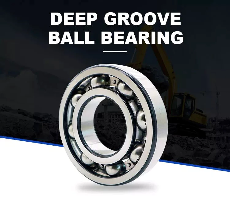
Advantages of Ball Bearings

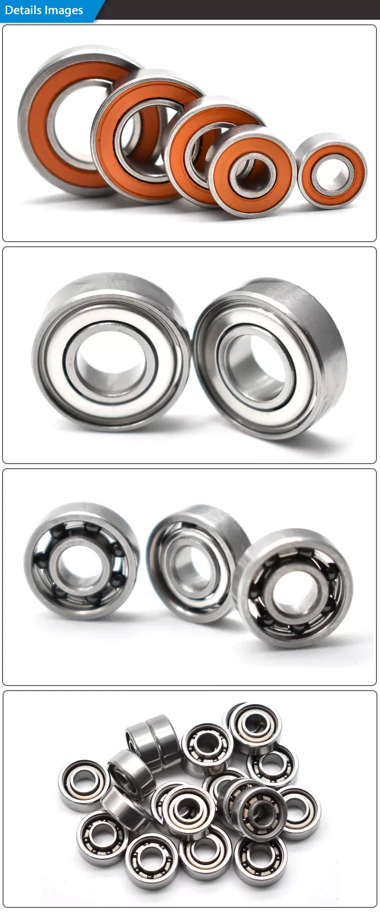
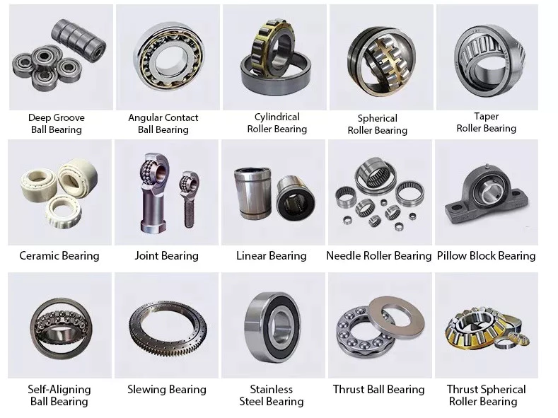
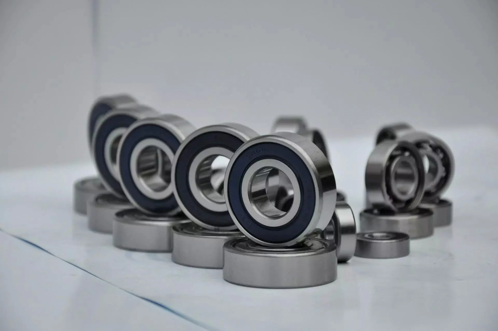
What is a ball bearing? A ball bearing is a type of rolling-element bearing that utilizes balls to maintain separation between 2 bearing races. Its contact angle between the balls and the races helps it reduce friction between the loads. There are several advantages to ball bearings, including their ability to withstand water. Read on to learn more. Here are a few of the benefits. You can use them in your daily life, from your car to your boat.

Ball bearings reduce friction between loads

Ball bearings reduce friction between loads by constraining the relative motion between moving parts. These bearings consist of a ring of small metal balls that reduce friction between moving objects. The name "ball bearing" is derived from the verb "to bear." The lubricant within the bearing reduces friction between moving particles. In a machine, ball bearings reduce friction between moving parts and improve linear motion around a fixed axis.
These bearings are commonly used to reduce friction between loads in rotating machines. They have 2 tracks, 1 fixed to the rotating part and 1 stationary. The rolling balls of a ball bearing have lower friction than flat surfaces. Because of this, they are useful for bar stool bearings. They reduce friction between surfaces and maintain the separation between bearing races. Hence, minimal surface contact is possible. Ball bearings have the potential to increase the life of machines and reduce energy consumption.
Ball bearings can be as small as a wrist watch or as large as an industrial motor. They function the same way, reducing friction between loads. Among their many uses, ball bearings are essential for everyday operations. Clocks, air conditioners, fans, and automobile axles all use ball bearings. In fact, anything that uses a motor requires ball bearings. It's no wonder they're gaining popularity in industries and everyday life.
bearing

They support radial and axial loads

Radial ball bearings are used primarily for radial loads, but they also have a capacity for axial load. This load capacity is usually given as a percentage of the radial load rating. Axial load capacity is generally greater for a bearing with a larger difference between the inner and outer ring diameters. The axial load capacity is also affected by the bearing's raceway depth, with shallow raceways being more suitable for heavier axial loads.
The 2 main types of axial and radial loads are defined by their orientation. Axial loads apply forces in 1 direction while radial loads act on the opposite direction. In both cases, the bearing must support the forces that are imposed. Axial loads apply forces to a bearing in a single direction, while radial loads apply forces in both directions. Regardless of the type of load, axial and radial loads should be considered when selecting a bearing for a given application.
Angular and radial ball bearings differ in their materials. Radial ball bearings are made largely of through-hardened materials. They typically have a Rockwell hardness rating of 58 Rc. The raceways and balls of these bearings are made of 440C stainless steel. They may also contain shields and seals. SAE 52100 steel is the most common material for the raceway, while molybdenum steels are excellent for high temperatures.

They have a contact angle between the balls and the races

When comparing axial load bearings with their radial counterparts, the angular contact angle is more important. Axial load bearings, have a contact angle between the balls and the races of 35 degrees. They are suitable for axial loads and a limited radial load. The contact angle of these bearings is a result of the shape of the inner and outer rings. Each rolling element comes into contact with the inner and outer rings only at 1 point, forming a 30 degree angle with the radial plane. The radial force of the axial load on these bearings is therefore increased by increasing the contact angle between the balls and the races.
This contact angle determines the amount of friction between the balls and the races, and allows angular contact bearings to withstand heavy radial and thrust loads. In addition, the larger the contact angle, the greater the axial load support. Angular contact bearings come in standard imperial (inch) and metric (mm) sizes. The angular contact angle is determined by the free radial play value and the curvature of the inner track.

They are water-resistant

In addition to their water-resistant qualities, corrosion-resistant ball bearings can also protect against the damaging effects of corrosive environments. Generally, standard metals, such as steel, are susceptible to rust, which can significantly reduce their performance and extend the life of parts. However, plastics, stainless steel, and ceramics can provide corrosion-resistant ball bearings. And because these materials are much more durable, they offer other advantages, such as being easy to maintain.
Among the advantages of plastic ball bearings is their high resistance to extreme temperatures, high speeds, and corrosion. Depending on their construction, plastic bearings are often able to resist corrosion and anti-static properties. They're lightweight and inexpensive compared to steel ball bearings. CZPT Sales Corporation was established in 1987 with a modest turnover of 4 lacs. As of the last financial year, it has grown to 500 lacs in sales.
Other advantages of water-resistant ball bearings include corrosion resistance, which is a key consideration in many applications. While stainless steel is highly corrosion-resistant, it decreases the bearing's load-carrying capacity. Also, corrosion-resistant deep groove ball bearings are usually made with a specified internal clearance, which absorbs loss in clearance during mounting and shaft expansion. This factor affects their performance, and if these are compromised, a replacement may be necessary.
bearing

They are tough

A few things make ball bearings tough: they're made of real materials, which means that they have inherent imperfections. Grade-1 balls are made especially for high-stress applications, such as Formula One engines. Grade-3 balls, on the other hand, strike the perfect balance between performance and cost. Ceramic balls, for example, are made to spin at a high rate of 400 RPM, and they're finished with a mirror finish.
A steel carbon ball bearing is 1 of the toughest forms of ball bearings available. The material is incredibly strong, but the contact between the balls isn't the best. Low-carbon steel is best for linear shafting and is usually coated with a polymer to prevent damage. Steel ball bearings with moderate amounts of carbon are tough, durable, and water-resistant. They're ideal for gears, but their high-carbon steel counterparts are particularly tough and can resist corrosion.
A ceramic ball bearing is another option. This type has steel inner and outer rings but ceramic balls. Ceramic balls can withstand higher temperatures than steel and are also electrically insulating. Ceramic ball bearings also tend to be lighter and are more resistant to wear and tear. They're also ideal for applications in which grease is not an option, such as in space shuttles. Despite the fact that ceramic ball bearings are tough, they're still cheaper than steel ball bearings.

They are conductive

You may have heard the term "ball bearing" if you've studied introductory physics. What does that mean? Essentially, ball bearings are conductive because of their ability to conduct electricity. This ability is reflected in the charge distribution on the surface of the ball. Positive charges are drawn toward the positive plate, while negative charges are drawn away from the positively charged ball bearing. You may have even seen a ball bearing in action.
However, despite their conductive nature, ball bearings can still become damaged by electrical discharge. A higher voltage can cause the balls to pit, and the raceways to become uneven. These uneven surfaces will first show up as excessive noise, and eventually cause the bearing to malfunction. Fortunately, engineers have found a way to counter this problem: conductive grease. This grease enables current to flow through the ball bearing, preventing both heat and voltage buildup.
The difference between steel and ceramic ball bearings is their density. Steel bearings are more conductive than glass or hybrid ceramics. Steel ball bearings have an even grain structure and are conductive for resonance flow. When moving fast, the air surrounding the steel ball bearing carries resonance from the inner ring to the outer. This makes them ideal for high-speed resonance transfer. In addition to being conductive, glass microbeads are harder and lighter than steel.
bearing

They are used in pulley systems

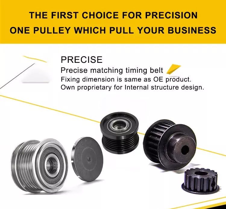
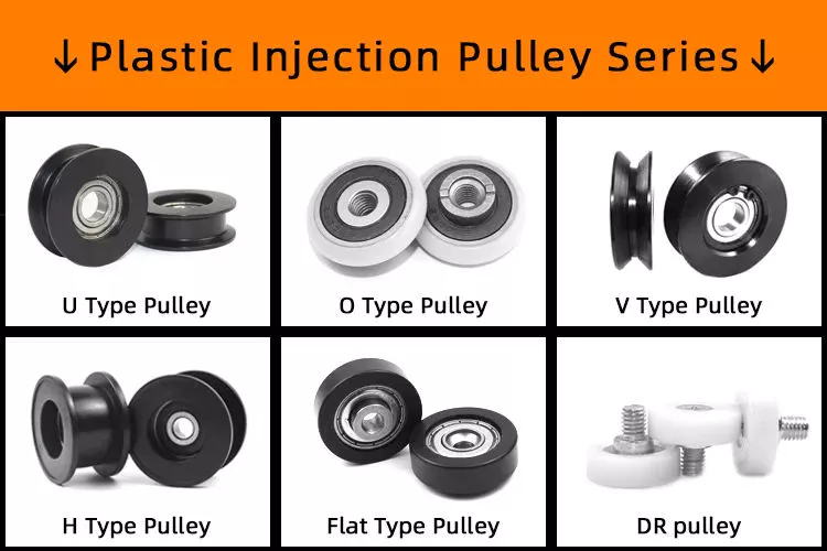
Pulley systems use ball bearings to move the sprocket, which is a wheel that rotates. These bearings are installed on the center mounting hole of the pulley wheel. They protect the entire system from heat, while allowing higher speed and smooth operation. They distribute the weight of the load evenly, minimizing friction and wobbling, and ensure a smooth rotation. Ball bearings are typically made from steel and are installed inside the pulley wheel.
The moment of inertia and bearing friction are measured to within 10 percent accuracy. These 2 variables affect the speed of the pulley system, which can lead to crashes if the weight holders are not balanced. Therefore, ball bearings are used to minimize the chance of such crashes. When you want to know more about ball bearings in pulley systems, here are the advantages they provide.
Another benefit of ball bearings in pulley systems is that they have lower friction than their solid counterparts. In order to reduce friction, however, ball bearings must be made of good materials. Some of the common ball materials are high-quality plastics and stainless steel. Good materials and clever block design are essential to minimizing friction. If you are planning to use ball bearings in your pulley system, check out the following tips and make sure you are choosing the right 1 for your application.
China manufacturer Europe Small/Mini Compact 4WD Articulated Front End Tractor 1ton/1.5ton/2 Ton Telescopic Boom Wheel Loaders for Farming/Construction/Gardening     with Good qualityChina manufacturer Europe Small/Mini Compact 4WD Articulated Front End Tractor 1ton/1.5ton/2 Ton Telescopic Boom Wheel Loaders for Farming/Construction/Gardening     with Good quality

China Professional Liftor/Foton/Yto/Kubata 20/60HP 604 Hand Rotary Electric Power Tiller Price Compact Mini Small Tractor Farm Walking Garden Agricultural Machinery Tractor with Free Design Custom

Product Description

LIFTOR/Foton/YTO/Kubata 60HP 604 Hand Rotary Electric Power Tiller Price Compact Mini Small Tractor Farm Walking Garden Tractor Agricultural Machinery
 

NBS chassis tractor is a group tractor for general purpose. It can be used in plain, hill, mountain area,
paddy field, orchard, grassland and meadow.It can accomplish various farm tools such as plow, harrow,
planter, harvester and trailer,etc. Following is TY chassis tractor details, please check.

LIFTOR Tractor Features:

1. CZPT series tractor is designed for multiple light works, such as farming, transportation etc.

2. Equipped with Chinese famous diesel engine, It has the advantage of high cost efficiency and fuel    efficiency, low maintenance cost and good working performance.

3. Using central console and mature structure, the tractor is easy to control and maintain.

4. 8F+2R gearbox with easy operation and convenient maintenance;

5. Optional single/double action clutches for different needs and operation;

6. Optional Herringbone tires, paddy tires or other type of tires to meet your needs of working conditions.

7. Hydraulic power steering(4WD) makes it easy to control and reduce the labor strength of operator.

Tractor Parameter:
 

Model

HX504

HX604

Wheel Drive

4x4

4x4

Horse Power

50 HP

60 HP

Chassis Model

Small HangZhou Chassis

Tractor With Roll Bar and Roof Dimension(LxWxH)

3550x1650x2360 mm

Tractor With Warm Wind Cabin Dimension(LxWxH)

3550x1650x2460 mm

Minimum Service Quality

1860 kgs

1940kgs

Front Wheel Tread

1300 mm

Rear Wheel Tread

1300 mm

Wheel Base

1850 mm

Minimum Ground Clearance

365 mm

Gear Shifts

8F + 2R

Tire Size

6.5-16/11.2-24 Inch

Engine Specification

Engine Brand

Quanchai

Xinchai

Emission Standard

3

Engine Model

4B5-50V32

4D27ZT32

Type

Water Cooled Four Cylinders In-line Engine

Rated Power

36.8kw

44.2kw

Rated Revolution

2400 r/min

Start Way

Electric Start

Gear Box

(4+1)x2

Clutch

Single Action

PTO Speed

Double Speed,  6 Splines

LIFTOR Tractor Pictures:

Optional Implements for Tractor :

About US:

"Liftor Enterprises" is a high-tech enterprise professionally specialized in R&D, production, sales, service of electric storage,intelligent industrial system, agriculatural tractor, lifting machine and wheel loader. It is located in HangZhou, ZheJiang Province with advanced forklift manufacturer technology, processing equipment and perfect product testing center.

Our company is the China Automobile Industry Association member unit. We won the honorary title such as "Outstanding Enterprise of Quality Management, Credibility and Service AAA level", "National Enterprise of Good Creditworthiness", "National Quality Management Advanced Enterprise" etc. The company has already passed the safety production standardization and the quality authentication of ISO9001:2008 and European Union CE certification, fit-out national patent certificate.

Our main equipment are agriculatural tractor, lifting machine, wheel loader and forklift. It is widely used in various places of modern logistics.


FAQ:

1. Manufacturer or Trading Company?
We are leading tractor manufacturer for 20 years, and specialize in 12-240Hp tractors in China.

2. MOQ: Mini tractor: 8 units; Middle tractor(25-40hp): 2 units; Above 50hp: 1 unit

3. Spare Parts: Free toolbox and easy damaged parts.

4. Shippment: We can help you arrange shippment.

5. Delivery Time: Usually 25 days. In CZPT season,30-40 days

6. Warranty Time: Complete service system, 12 months since arrival of destination port

7. Payment Terms: We accept 30%T/T in advance, and 70% T/T before delivery

8. Tractor Options: Can be equipped with ROPS, Canopy, Cabin, AC Cabin, Air Brakes, Hydraulic Valve Out, Paddy Tire or as per your requirements.

9. Tractor Logo: We have our own logo. And we also can put your logo for free.

10. Package and Loading: (1).complete tractor package: 2 units/20GP, 4 units/40HQ;(2).Iron Frame Package: 8 units/20GP, 16 units/40HQ

11. Tractor Implements: Rotary tiller, disc plow, furrow plow, cultivator, front end Loader, backhoe, Mower, Trailer, Snow Blower or as per your requirements.

12. Part supply: Complete Parts Workshop, and can supply all parts

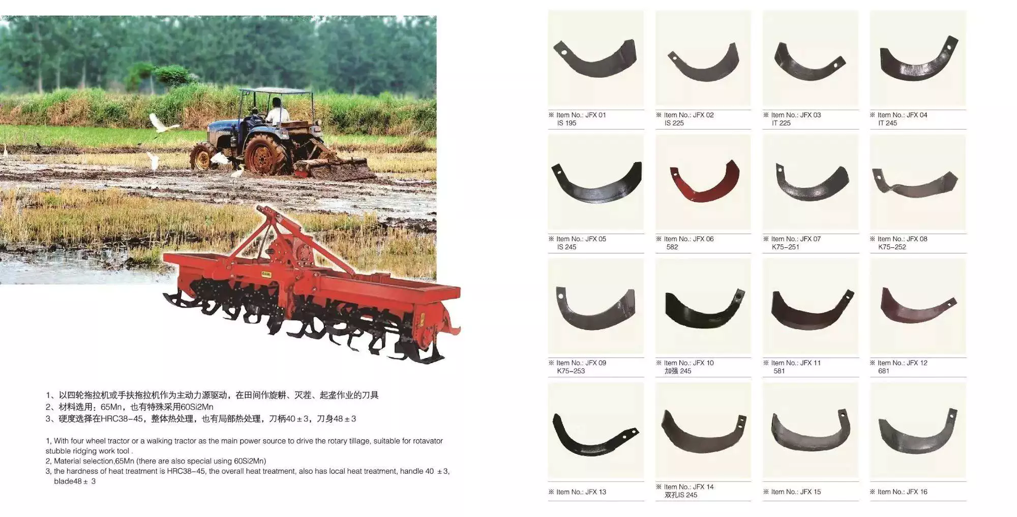
Agricultural Parts

Agricultural machinery, also known as agricultural machinery, is any mechanical device or structure used in agriculture . It includes hand tools, tractors and countless other farm implements. Agricultural machinery can be divided into 2 categories: power tools and hand tools. Some of the most common types of agricultural equipment are listed below. Each of these categories includes parts used to repair, maintain, and operate a specific piece of equipment or machinery. To learn more about agricultural machinery, please visit the Manufacturers and Suppliers section of our website.
agriculturalparts

Agricultural Machinery

Agricultural machinery parts are critical to the overall operation of a farm or ranch. Replacement parts are essential if your equipment is not functioning as expected. CZPT's consumables experts are ready to help you find the right replacement parts for your equipment. You can rely on our knowledgeable staff to provide you with fast and accurate replacement services. If your agricultural machinery needs replacement parts, please contact us for assistance.
Key drivers of the agricultural machinery market include high global demand for food, rapid crop production, access to resources, and availability of credit. Agricultural machinery is mainly manufactured in Europe, the United States, Japan and China. Overall, we expect the agricultural machinery market to exceed $118 billion by 2025. Additionally, agricultural machinery OEM components are expected to grow at a CAGR of 3.6% over the next 5 years.
Agricultural machinery accessories include accessories and accessories other than tractor accessories. Plows loosen the soil and kill surface vegetation, fertilizer spreaders apply fertilizer evenly, rakes agitate the soil, and seeders sow seeds. Other accessories include balers, which collect materials and bundle them into management packs. Transplanters are used to transplant plants from 1 location to another. It must be properly maintained to maximize its useful life.
Farm machinery accessories can be found in all types of farming. From sowing to harvesting, farm machinery equipment is necessary to help farmers in various agricultural activities. Without mechanization, farming would not be as profitable as it is today. In Iran, Coulisse produces agricultural machinery parts including harrows, tillers, grain refiners, spinning machines and threshers. You can also find farm machinery accessories for sale through these companies.
A well-known brand in the field of agricultural machinery is New Holland. Parts can be found for New Holland and Case IH models. The company also produces replacement parts for many different models. The company's extensive dealer network spans more than 160 countries. PDF also supplies agricultural machinery parts for brands such as Ford and New Holland. If you are looking for reliable quality and cost-effective agricultural machinery, we can get the parts you need from these brands.

Agricultural Equipment

Growing population and demand for equipment drive the demand for agricultural equipment in Asia. In countries with limited land such as India, low-paying agricultural jobs are not enough for many farmers. At the same time, Australia has a large amount of agricultural land, but the reduction of agricultural labor has led to the increasing mechanization and integration of agricultural production. This, in turn, has fueled a surge in demand for Australian agricultural products in Asia, particularly in China and India.
Tractor transplanter is a common agricultural equipment. Tractors pull on these machines, which dig holes and put plants into the holes. A cultivator is another type of agricultural equipment that tills the soil and controls weeds. Smaller operations often use a cultivator. Large plastic farms, on the other hand, need to invest in cladding, using a series of wheels to lay down a layer of plastic.
Agricultural machinery is widely used. For example, tractors can carry heavy agricultural attachments such as haymakers and grain turbines. Farm equipment also helps farmers prepare soil for growing and harvesting large quantities of crops. It also helps transport food to other regions for processing. These machines make farming easier and more efficient. With all these benefits, it's no wonder so many people engage in farming as a profession. The world needs food and agriculture, and agricultural equipment is an integral part of the process.
Agricultural equipment operators use heavy agricultural machinery every day. They inspect the equipment and make minor repairs to keep it running smoothly. They also monitor the working environment and working conditions around the equipment. Depending on the field, agricultural equipment operators can operate a variety of agricultural equipment, load and unload products, and even harvest crops. These workers may spend most of the year working outdoors, which can take a long time. The average workweek for an agricultural equipment operator is approximately 18 hours.
Agricultural equipment operators often gain practical experience on the job. Some jobs in the industry may require a high school diploma, and students without a high school diploma can work on farms to learn the skills needed for the position. The industry requires employees to be properly trained and certified to operate equipment safely. AWS certification is highly recommended. All Associate of Applied Science in Agricultural Production Systems include core business and management courses applicable to the agricultural industry.
agriculturalparts

Agricultural machinery manufacturers

Agricultural machinery manufacturers produce agricultural implements such as tractors and combines for agricultural purposes. The production of these machines increases the productivity and efficiency of farmers around the world. These machines and parts increase the quality and quantity of crop production while reducing labor costs. They also help improve soil fertility. It's important to choose the right type of machine for your farm because not all farm machinery is the same. There are many high-quality agricultural machinery manufacturers in China, whose prices are competitive with the local market prices.
The growth of the agricultural machinery market is mainly driven by the growing global food demand. Agricultural equipment manufacturers are investing in precision-based technologies, which allow them to build better agricultural machines. In addition, OEM parts manufacturers focus on the safety, quality and continuous improvement of agricultural machinery parts. With the shift in focus, the agricultural machinery market is expected to make great strides in the coming years. Along with these improvements, the demand for agricultural machinery OEM parts is expected to grow at an annual rate of over 3%.
Yuantong Group: This agricultural machinery manufacturer has more than 20 overseas service centers around the world. The company is committed to providing excellent customer service and provides a warranty on all of its products. Yuantong Machinery's space parts are easily available at their service center. Shandong CZPT Heavy Industry International, a Chinese agricultural machinery manufacturer, was established in 1998 and is headquartered in Weifang City, Shandong Province.
Although the agricultural machinery industry is growing, the market is still affected by the economic downturn. The COVID-19 pandemic has put pressure on farming operations, who may forgo buying expensive equipment. Private investment in industrial equipment is also falling and is expected to decline further in 2020 and 2021. On the other hand, aftermarket agricultural machinery parts are tailored for an exact fit and outperform OEM parts.
agriculturalparts

Agricultural Machinery Suppliers

Agricultural Machinery Suppliers have a wide variety of products. From large farm machines to small ones, you'll find it all in 1 place. In addition to providing first-class machinery, agricultural machinery suppliers can also provide you with spare parts. Shandong Heavy Industry International, for example, is China's largest agricultural machinery maker, with annual sales of $9 billion. The company is headquartered in Weifang, Shandong and has been operating for more than 6 years.
Most farm equipment consists of hundreds of parts. For example, a typical tractor has more than 1,700 parts. Manufacturers have been shifting to just-in-time delivery of parts and raw materials. While the system works for predictable supply chains, it can break down when 1 component fails. Therefore, the best way to avoid problems and maximize profits is to get a list of Indian agricultural machinery suppliers through a dedicated marketplace.
Therefore, there are many suppliers of agricultural machinery. Some of the biggest names in the industry include CZPT and Caterpillar, both of which employ thousands of people. CZPT also offers a complete line of walk-behind and riding mowers, as well as log splitters and snow blowers. In addition, the German-made CZPT tractor line is being launched in Brazil. Finally, some smaller agricultural machinery enterprises produce and sell agricultural machinery.
In the next decade, the global agricultural machinery market will grow moderately. But in the short term, crop prices are expected to fall, which will negatively affect agricultural income and the agricultural machinery market. Experts predict that this will affect the demand for agricultural machinery. These factors will continue to influence the market and help farmers make better decisions. However, no single factor can guarantee that the agricultural machinery industry will not be affected by economic changes.
In addition to tractors, other types of agricultural machinery are also widely used for agricultural purposes. Tractors are the most common type of agricultural machinery and include rotary tillers, power tillers, subsoilers and trowels. Other equipment used for planting includes planters, planters and irrigation systems. Some specialized equipment includes sprinkler systems, micro sprinklers, and soil spray technology.

China Professional Liftor/Foton/Yto/Kubata 20/60HP 604 Hand Rotary Electric Power Tiller Price Compact Mini Small Tractor Farm Walking Garden Agricultural Machinery Tractor     with Free Design CustomChina Professional Liftor/Foton/Yto/Kubata 20/60HP 604 Hand Rotary Electric Power Tiller Price Compact Mini Small Tractor Farm Walking Garden Agricultural Machinery Tractor     with Free Design Custom

China Hot selling Chinese Lawn Mower Cheap Price 4X4 Mini Small Compact Agricultural Garden Farm Tractor with Front End Loader and Rear Backhoe Digger Auger for Sale From China wholesaler

Product Description

Product Description:

CP factory new 4x4 power steering side gears 40hp tractor
 

This model 40hp 4wd tractor sells very well for its good quality and cheap price.
We export this model tractors most to Europe, America, Australia and Brizil and other countries, they are very popular in the market.

With beautiful appearance, this tractor is also multi-functional. It can match all kinds of farming implements.

Pictures:

Standard Equipments: 

4L23 Engine,4 Cylinders,8+2 Gear Shift,With Single-Stage Clutch,Power Steering,Trailer outlet,
protection plate,Tires:6.0-16/9.5-24,hand throttle wire ,
4x4 Wheel Drive,Front Ballast,Rear Ballast,
3-Point Linkage, Rear PTO 540/760, Color follow your need.

Options:
Cab,Air Brake,Dual-Stage Clutch, 8+8 Shuttle Gear,11.2-24 Tires,
Tilting Draw Bar, Iron crate packing,

40hp 4wd Tractor Specs 
 

                     Model CP404
Dimensions of Tractor(mm) Length (to front ballast) 3300
Width 1560
Height (to the exhaust vent) 1896
Tread Front Wheel 1200
Rear Wheel 1200
Axle Base 1690
Min.Ground Clearance 300
Structure weight (kg) 1600
  Engine Model LD4L23
Type Vertical,4-Cylinder,Water Cooled and 4-stroke
Rated Power(kw) 29.4
Rated speed (r/min) 2400
Fuel Diesel
     Tires Front Wheel 6.00-16/6.5-16
Rear Wheel 9.5-24/11.2-24
Clutch Single-stage clutch
    Steering Hydraulic steering
    Transmission Type 8+2  shift
Suspension Type 3-point links
 PTO Type and Rev Semi-independent Type 720r/m or 540/760r/m
Spline Size I35 Rectangle Spline with 6 teeth

TZ-4 Front End Loader with 4 - in - 1 Bucket Specifications:

Model TZ-4
Bucket capacity(m3) 0.3
Rated Load(Kg) 360
Overall dimensions(mm) 4100×1600×1580
Max. dump height(mm) 2000
Max. dump distance(mm) 900
Bucket rollback angle (degree) 420
Max. unloading angle  (degree) 470
Max. scraping depth(mm) 140
Lifting time to pivot pin(s) 7
Descending time(s) 3.5
Recommended Tractor(hp) 35-50

LW-7 Backhoe Specifications:

Model LW-7
Bucket Capacity(m3) 0.036
Bucket Wide(mm) 400
Max.digging depth(mm) 2150
Max.digging Radius(mm) 3360
Max.digging Height(mm) 3400
Discharging Height(mm) 1760
Max.digging depth(2ft) Flat bottom(mm) 2000
Swing Angle(degree) 140°
Bucket Rotation(degree) 160°
Dipper stick CZPT Force(Kg) 950
Operating pressure(Mpa) 16

Packaging & Delivery:

-4 units inside 1x40'fcl assembled,
-Delivery time: 30 days after receiving your deposit

Company Information:

Our service:
1]. Color - Any color you like, we can paint it for you.
2]. Warranty time - We supply you 18 months warranty time.
3]. Spare Parts - For easy-damage parts, we will send you together with the tractor.
     In the warranty period, if spare parts don't work because of the quality, we will free send you new parts. 
4]. Delivery time: 20 days after receive your deposit.
5]. We can make the tractor with your logo in the order. (Free)
6]. Payment term: T/T30% in advance,70% T/T before shippment.or L/C at sight.

Certifications:

FAQ:


How to Assemble a Pulley System

A pulley is a wheel that rotates on a shaft or shaft to support the movement of a taut cable. Pulleys allow power to be transmitted from the shaft to the cable.
pulley

Simple pulley

The simplest theory of operation of a pulley system assumes that the rope and weight are weightless and that the rope and pulley are not stretched. Since the force on the pulley is the same, the force on the pulley shaft must also be zero. Therefore, the force exerted on the pulley shaft is also distributed evenly between the 2 wires passing through the pulley. The force distribution is shown in Figure 1.
The use of simple pulleys is as old as history. Before the Industrial Revolution, people relied on muscle strength to carry heavy loads. Pulleys, levers and ramps make this possible. Today, we can see pulleys in a variety of systems, from exercise equipment to garage doors, and even rock climbers use them to help them reach greater heights. As you can see, these simple machines have been around for centuries and are used in everyday life.
Another simple pulley system is the pulley system. In this system, there is a fixed pulley at the top and a movable pulley at the bottom. The 2 pulleys are connected by a rope. This combination reduces the amount of work required to lift the load. Additionally, the ropes used in this system are usually made of rope and woven through the individual wheels of the pulley drum.
A pulley is an ingenious device that distributes weight evenly and can be used to lift heavy objects. It is easy to build and can be easily modified for a wide range of activities. Even young children can make their own with very few materials. You can also use simple household items such as washing machines, thin textbooks and even chopsticks. It's very useful and can be a great addition to your child's science and engineering activities.
The simplest pulley system is movable. The axis of the movable pulley can move freely in space. The load is attached to 1 end of the pulley and the other end to the stationary object. By applying force on the other end of the rope, the load is lifted. The force at the other end of the rope is equal to the force at the free end of the pulley.
Another form of pulley is the compound pulley. Compound pulleys use 2 or more wheels to transmit force. Compound pulleys have 2 or more wheels and can lift heavier objects. Dim is POLE2.
pulley

tapered pulley

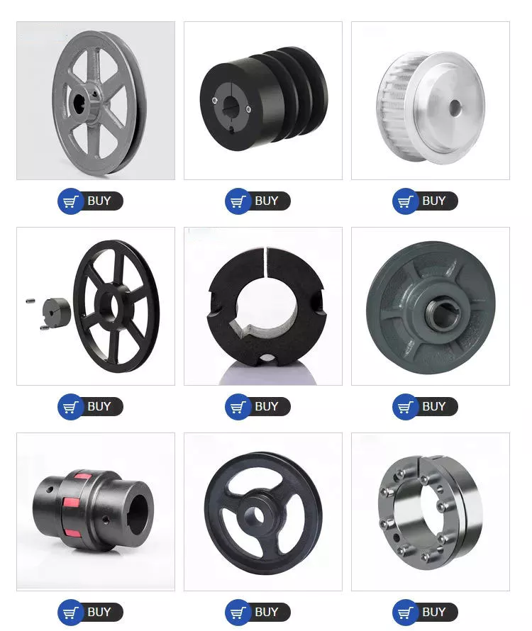
It is important to clean and align the bolt holes before assembling the tapered pulley. The screws should be lubricated and the threads cleaned before installation. To install the pulley, insert it into the shaft keyway. The keyway should be aligned with the shaft hole to prevent foreign matter from entering the pulley. Then, alternately tighten the bolts until the pulley is tightened to the desired torque.
A tapered pulley is a basic structure. The pulley belt is arranged across 4 steps. Installed between the headstock casting and the main shaft, it is often used in the paper industry. It integrates with printing machinery and supports assembly lines. These pulleys are also available in metric range options, eliminating the need for ke-waying or re-drilling. They are easy to install, and users can even customize them to suit their needs.
CZPT Private Limited is a company that provides unique products for various industries. This large product is used for many different purposes. Also, it is manufactured for industrial use. The company's website provides detailed specifications for the product. If you need a tapered pulley, contact a company in your area today to purchase a quality product!
Tapered pulleys are vital to paper mill machinery. Its special design and construction enable it to transmit power from the engine source to the drive components. The advantages of this pulley include low maintenance costs and high mechanical strength. Cone wheel diameters range from 10 inches to 74 inches. These pulleys are commonly used in paper mills as they offer low maintenance, high mechanical strength and low wear.
A tapered sleeve connects the pulley to the shaft and forms an interference fit connector. The taper sleeve is fixed on the shaft with a key, and the corresponding inner hole is fixed on the shaft with a key. These features transmit torque and force to the pulley through friction. This allows the tapered pulley to move in a circular motion. The torque transfer characteristics of this pulley are most effective in high speed applications.
The sleeve is the most important part when assembling the tapered pulley. There is an 8-degree taper inside the cone, which is closely connected to the inner surface of the pulley. Taper sleeves and pulleys are interchangeable. However, tapered pulleys can be damaged after prolonged use.
pulley

pulley pulley system

A pulley pulley system is a great way to move heavy objects. These systems have been around for centuries, dating back to the ancient Greeks. This simple mechanism enables a person to lift heavy objects. These blocks are usually made of rope, and the number of turns varies for different types of rope. Some blocks have more cords than others, which creates friction and interferes with the easy movement of the lifting system.
When using a pulley pulley, the first thing to decide is which direction to pull. Unfavorable rigging means pulling in the opposite direction. In theory, this method is less efficient, but sometimes requires a certain amount of work space. The benefit is that you will increase the mechanical advantage of the pulley by pulling in the opposite direction. So the interception and tackle system will give you more of a mechanical advantage.
Pulley pulleys are an excellent choice for lifting heavy objects. The system is simple to install and users can easily lift objects without extensive training. Figure 3.40 shows a pulley in action. In this photo, the person on the left is pulling a rope and tying the end of the rope to a weight. When the rope is attached to the load, the rope will be pulled over the pulley and pulley.
The blocks on the blocks are attached to the ends of the rope. This creates unique lifting advantages compared to single-line systems. In Figure 3, the tension of each thread is equal to one-third of the unit weight. When the rope is pulled over the pulley, the force is divided equally between the 2 wires. The other pulley reverses the direction of the force, but that doesn't add any advantage.
Use pulleys to reduce traction and load. The weight of the load has not changed, but the length of the rope has increased. Using this method, lifting the load by pulling the rope 4 times reduces the force required to lift 1 foot. Likewise, if the pulley system had 4 pulleys instead of three, the length of the rope would be tripled.
The system can transmit loads in any direction. Rope length is determined by multiplying the distance from the fixed block to the load by the mechanical advantage. If the mechanical advantage is 3:1, then passing the rope through the pulley 3 times will produce the required traction distance. Also, the length of the rope will depend on the mechanical advantage, so if the load is 3 times the length of the rope, it will be more than 3 times the required length.

China Hot selling Chinese Lawn Mower Cheap Price 4X4 Mini Small Compact Agricultural Garden Farm Tractor with Front End Loader and Rear Backhoe Digger Auger for Sale From China     wholesaler China Hot selling Chinese Lawn Mower Cheap Price 4X4 Mini Small Compact Agricultural Garden Farm Tractor with Front End Loader and Rear Backhoe Digger Auger for Sale From China     wholesaler

China factory China 60HP Agricultural Tractor with All Kinds of Accessories near me shop

Product Description

Product Description:

60 hp China manufacturer 60hp 4wd farming 4x4 tractors for agriculture
 

This model 60hp 4wd tractor sells very well for its good quality and cheap price.
We export this model tractors most to Europe, America, Australia and Brizil and other countries, they are very popular in the market.

With beautiful appearance, this tractor is also multi-functional. It can match all kinds of farming implements.

Pictures:

Standard Equipments: 

QC4102 Engine,4 Cylinders,12+12 Gear Shift,With Dual-Stage Clutch,Power Steering,Trailer outlet,
protection plate,Tires:8.3-20/12.4-28,hand throttle wire ,4x4 Wheel Drive,3-Point Linkage,
Rear PTO 540/760, Color follow your need.

Options:
Cab,Canopy,Multi-Way Valve,Air Brake,Front Ballast,Rear Ballast,Tilting Draw Bar, 

60hp 4wd Tractor Specs 
 

                     Model CP604
Dimensions of Tractor(mm) Length 3900
Width 1800
Height (to the exhaust vent) 2160
Tread Front Wheel 1300
Rear Wheel 1300
Axle Base 1760
Min.Ground Clearance 360
Structure weight (kg) 2580Kg
  Engine Model QC4102
Type Vertical,4-Cylinder,Water Cooled and 4-stroke
Rated Power(kw) 44.4
Rated speed (r/min) 2400
Fuel Diesel
     Tires Front Wheel 8.3-20
Rear Wheel 12.4-28
Clutch Dual-stage clutch
    Steering Hydraulic steering
    Transmission Type 12+12  shift
Suspension Type 3-point links
 PTO Type and Rev Semi-independent Type 720r/m or 540/720r/m
Spline Size I38 Rectangle Spline with 8 teeth

TZ-8 Front End Loader with 4 - in - 1 Bucket Specifications:

Model TZ-8
Bucket capacity(m3) 0.43
Rated Load(Kg) 360
Overall dimensions(mm) 4900×1740×1296
Max. dump height(mm) 2200
Max. dump distance(mm) 960
Bucket rollback angle (degree) 420
Max. unloading angle  (degree) 460
Max. scraping depth(mm) 160
Lifting time to pivot pin(s) 8
Descending time(s) 4
Recommended Tractor(hp) 50-70

LW-8 Backhoe Specifications:

Model LW-8
Bucket Capacity(m3) 0.048
Bucket Wide(mm) 450
Max.digging depth(mm) 2640
Max.digging Radius(mm) 3930
Max.digging Height(mm) 3510
Discharging Height(mm) 2000
Max.digging depth(2ft) Flat bottom(mm) 2500
Swing Angle(degree) 140°
Bucket Rotation(degree) 160°
Dipper stick CZPT Force(Kg) 1000
Operating pressure(Mpa) 16

Packaging & Delivery:

-3 units inside 1x40'fcl assembled,
-Delivery time: 30 days after receiving your deposit

Company Information:

Our service:

Certifications:

FAQ:


How to Determine the Quality of a Worm Shaft

There are many advantages of a worm shaft. It is easier to manufacture, as it does not require manual straightening. Among these benefits are ease of maintenance, reduced cost, and ease of installation. In addition, this type of shaft is much less prone to damage due to manual straightening. This article will discuss the different factors that determine the quality of a worm shaft. It also discusses the Dedendum, Root diameter, and Wear load capacity.
worm shaft

Root diameter

There are various options when choosing worm gearing. The selection depends on the transmission used and production possibilities. The basic profile parameters of worm gearing are described in the professional and firm literature and are used in geometry calculations. The selected variant is then transferred to the main calculation. However, you must take into account the strength parameters and the gear ratios for the calculation to be accurate. Here are some tips to choose the right worm gearing.
The root diameter of a worm gear is measured from the center of its pitch. Its pitch diameter is a standardized value that is determined from its pressure angle at the point of zero gearing correction. The worm gear pitch diameter is calculated by adding the worm's dimension to the nominal center distance. When defining the worm gear pitch, you have to keep in mind that the root diameter of the worm shaft must be smaller than the pitch diameter.
Worm gearing requires teeth to evenly distribute the wear. For this, the tooth side of the worm must be convex in the normal and centre-line sections. The shape of the teeth, referred to as the evolvent profile, resembles a helical gear. Usually, the root diameter of a worm gear is more than a quarter inch. However, a half-inch difference is acceptable.
Another way to calculate the gearing efficiency of a worm shaft is by looking at the worm's sacrificial wheel. A sacrificial wheel is softer than the worm, so most wear and tear will occur on the wheel. Oil analysis reports of worm gearing units almost always show a high copper and iron ratio, suggesting that the worm's gearing is ineffective.

Dedendum

The dedendum of a worm shaft refers to the radial length of its tooth. The pitch diameter and the minor diameter determine the dedendum. In an imperial system, the pitch diameter is referred to as the diametral pitch. Other parameters include the face width and fillet radius. Face width describes the width of the gear wheel without hub projections. Fillet radius measures the radius on the tip of the cutter and forms a trochoidal curve.
The diameter of a hub is measured at its outer diameter, and its projection is the distance the hub extends beyond the gear face. There are 2 types of addendum teeth, 1 with short-addendum teeth and the other with long-addendum teeth. The gears themselves have a keyway (a groove machined into the shaft and bore). A key is fitted into the keyway, which fits into the shaft.
Worm gears transmit motion from 2 shafts that are not parallel, and have a line-toothed design. The pitch circle has 2 or more arcs, and the worm and sprocket are supported by anti-friction roller bearings. Worm gears have high friction and wear on the tooth teeth and restraining surfaces. If you'd like to know more about worm gears, take a look at the definitions below.
worm shaft

CZPT's whirling process

Whirling process is a modern manufacturing method that is replacing thread milling and hobbing processes. It has been able to reduce manufacturing costs and lead times while producing precision gear worms. In addition, it has reduced the need for thread grinding and surface roughness. It also reduces thread rolling. Here's more on how CZPT whirling process works.
The whirling process on the worm shaft can be used for producing a variety of screw types and worms. They can produce screw shafts with outer diameters of up to 2.5 inches. Unlike other whirling processes, the worm shaft is sacrificial, and the process does not require machining. A vortex tube is used to deliver chilled compressed air to the cutting point. If needed, oil is also added to the mix.
Another method for hardening a worm shaft is called induction hardening. The process is a high-frequency electrical process that induces eddy currents in metallic objects. The higher the frequency, the more surface heat it generates. With induction heating, you can program the heating process to harden only specific areas of the worm shaft. The length of the worm shaft is usually shortened.
Worm gears offer numerous advantages over standard gear sets. If used correctly, they are reliable and highly efficient. By following proper setup guidelines and lubrication guidelines, worm gears can deliver the same reliable service as any other type of gear set. The article by Ray Thibault, a mechanical engineer at the University of Virginia, is an excellent guide to lubrication on worm gears.

Wear load capacity

The wear load capacity of a worm shaft is a key parameter when determining the efficiency of a gearbox. Worms can be made with different gear ratios, and the design of the worm shaft should reflect this. To determine the wear load capacity of a worm, you can check its geometry. Worms are usually made with teeth ranging from 1 to 4 and up to twelve. Choosing the right number of teeth depends on several factors, including the optimisation requirements, such as efficiency, weight, and centre-line distance.
Worm gear tooth forces increase with increased power density, causing the worm shaft to deflect more. This reduces its wear load capacity, lowers efficiency, and increases NVH behavior. Advances in lubricants and bronze materials, combined with better manufacturing quality, have enabled the continuous increase in power density. Those 3 factors combined will determine the wear load capacity of your worm gear. It is critical to consider all 3 factors before choosing the right gear tooth profile.
The minimum number of gear teeth in a gear depends on the pressure angle at zero gearing correction. The worm diameter d1 is arbitrary and depends on a known module value, mx or mn. Worms and gears with different ratios can be interchanged. An involute helicoid ensures proper contact and shape, and provides higher accuracy and life. The involute helicoid worm is also a key component of a gear.
Worm gears are a form of ancient gear. A cylindrical worm engages with a toothed wheel to reduce rotational speed. Worm gears are also used as prime movers. If you're looking for a gearbox, it may be a good option. If you're considering a worm gear, be sure to check its load capacity and lubrication requirements.
worm shaft

NVH behavior

The NVH behavior of a worm shaft is determined using the finite element method. The simulation parameters are defined using the finite element method and experimental worm shafts are compared to the simulation results. The results show that a large deviation exists between the simulated and experimental values. In addition, the bending stiffness of the worm shaft is highly dependent on the geometry of the worm gear toothings. Hence, an adequate design for a worm gear toothing can help reduce the NVH (noise-vibration) behavior of the worm shaft.
To calculate the worm shaft's NVH behavior, the main axes of moment of inertia are the diameter of the worm and the number of threads. This will influence the angle between the worm teeth and the effective distance of each tooth. The distance between the main axes of the worm shaft and the worm gear is the analytical equivalent bending diameter. The diameter of the worm gear is referred to as its effective diameter.
The increased power density of a worm gear results in increased forces acting on the corresponding worm gear tooth. This leads to a corresponding increase in deflection of the worm gear, which negatively affects its efficiency and wear load capacity. In addition, the increasing power density requires improved manufacturing quality. The continuous advancement in bronze materials and lubricants has also facilitated the continued increase in power density.
The toothing of the worm gears determines the worm shaft deflection. The bending stiffness of the worm gear toothing is also calculated by using a tooth-dependent bending stiffness. The deflection is then converted into a stiffness value by using the stiffness of the individual sections of the worm shaft. As shown in figure 5, a transverse section of a two-threaded worm is shown in the figure.

China factory China 60HP Agricultural Tractor with All Kinds of Accessories     near me shop China factory China 60HP Agricultural Tractor with All Kinds of Accessories     near me shop

China Best Sales All Kinds of China Brand Yto Tractor Parts for Sale with Free Design Custom

Product Description

Product Description:

25hp cheap 4x4 mini tractor
 

This model 25hp 4wd tractor sells very well for its good quality and cheap price.
We export this model tractors most to Europe, America, Australia and Brizil and other countries, they are very popular in the market.

With beautiful appearance, this tractor is also multi-functional. It can match all kinds of farming implements.

Pictures:


Standard Equipments: 

LD385 Engine,4 Cylinders,8+2 Gear Shift,With Single-Stage Clutch,Power Steering,Trailer outlet,
protection plate,Tires:6.0-16/9.5-24,hand throttle wire ,
4x4 Wheel Drive,Front Ballast,Rear Ballast,
3-Point Linkage, Rear PTO 540/760, Color follow your need.

Options:
Cab,Canopy,Multi-Way Valve,Air Brake,Dual-Stage Clutch, 8+8 Shuttle Gear,11.2-24 Tires,
Tilting Draw Bar, Combination Instrument,Iron crate packing,

25hp 4wd Tractor Specs 
 

                     Model CP254
Dimensions of Tractor(mm) Length (to front ballast) 3300
Width 1560
Height (to the exhaust vent) 1896
Tread Front Wheel 1200
Rear Wheel 1200
Axle Base 1690
Min.Ground Clearance 300
Structure weight (kg) 1300
  Engine Model LD385
Type Vertical,4-Cylinder,Water Cooled and 4-stroke
Rated Power(kw) 18.4
Rated speed (r/min) 2400
Fuel Diesel
     Tires Front Wheel 6.00-16/6.5-16
Rear Wheel 9.5-24/11.2-24
Clutch Single-stage clutch
    Steering Hydraulic steering
    Transmission Type 8+2  shift
Suspension Type 3-point links
 PTO Type and Rev Semi-independent Type 720r/m or 540/760r/m
Spline Size I35 Rectangle Spline with 6 teeth

Packaging & Delivery:

-4 units inside 1x40'fcl assembled,
-Delivery time: 30 days after receiving your deposit

Company Information:

Our service:

Certifications:

FAQ:


Screw Shaft Types

A screw shaft is a cylindrical part that turns. Depending on its size, it is able to drive many different types of devices. The following information outlines the different types of screws, including their sizes, material, function, and applications. To help you select the right screw shaft, consider the following factors:
screwshaft

Size

A screw can come in a variety of shapes and sizes, ranging from a quarter to a quarter-inch in diameter. A screw is a cylindrical shaft with an inclined plane wrapped around it, and its main function is to fasten objects together by translating torque into a linear force. This article will discuss the dimensions of screws and how to determine the size of a screw. It is important to note that screw sizes can be large and small depending on the purpose.
The diameter of a screw is the diameter of its shaft, and it must match the inner diameter of its nuts and washers. Screws of a certain diameter are also called machine screws, and they can be larger or smaller. Screw diameters are measured on the shaft underneath the screw head. The American Society of Mechanical Engineers (ASME) standardized screw diameters in 3/50-inch to 16 (3/8-inch) inches, and more recently, sizes were added in U.S. fractions of an inch. While shaft and head diameters are standardized, screw length may vary from job to job.
In the case of the 2.3-mm screw group, the construct strength was not improved by the 1.2-mm group. The smaller screw size did not increase the strength of the construct. Further, ABS material did not improve the construct strength. Thus, the size of screw shaft is an important consideration in model design. And remember that the more complex your model is, the larger it will be. A screw of a given size will have a similar failure rate as a screw of a different diameter.
Although different screw sizes are widely used, the differences in screw size were not statistically significant. Although there are some limitations, screws of different sizes are generally sufficient for fixation of a metacarpal shaft fracture. However, further clinical studies are needed to compare screw sizes for fracture union rates. So, if you are unsure of what size of screw shaft you need for your case, make sure to check the metric chart and ensure you use the right one.
screwshaft

Material

The material of a screw shaft plays an important role in the overall performance of a screw. Axial and central forces act to apply torque to the screw, while external forces, such as friction, exert a bending moment. The torsional moments are reflected in the torque, and this causes the screw to rotate at a higher rate than necessary. To ensure the longevity of the screw, the material of the screw shaft should be able to handle the bending moment, while the diameter of the shaft should be small enough to avoid causing damage.
Screws are made from different metals, such as steel, brass, titanium, and bronze. Manufacturers often apply a top coating of chromium, brass, or zinc to improve corrosion resistance. Screws made of aluminum are not durable and are prone to rusting due to exposure to weather conditions. The majority of screw shafts are self-locking. They are suited for many applications, including threaded fasteners, C-clamps, and vises.
Screws that are fabricated with conical sections typically feature reduced open cross-sectional areas at the discharge point. This is a key design parameter of conical screw shafts. In fact, reductions of up to 72% are common across a variety of applications. If the screw is designed to have a hard-iron hanger bearing, it must be hardened. If the screw shaft is not hardened, it will require an additional lubricant.
Another consideration is the threads. Screw shafts are typically made of high-precision threads and ridges. These are manufactured on lathes and CNC machines. Different shapes require different materials. Materials for the screw shaft vary. There are many different sizes and shapes available, and each 1 has its own application. In addition to helical and conical screw shafts, different materials are also available. When choosing material, the best 1 depends on the application.
The life of the screw depends on its size, load, and design. In general, the material of the screw shaft, nut body, and balls and rollers determine its fatigue life. This affects the overall life of the screw. To determine whether a specific screw has a longer or shorter life, the manufacturer must consider these factors, as well as the application requirements. The material should be clean and free of imperfections. It should be smooth and free of cracks or flaking, which may result in premature failure.

Function

The function of a screw shaft is to facilitate the rotation of a screw. Screws have several thread forms, including single-start, double-start and multi-start. Each form has its own advantages and disadvantages. In this article we'll explore each of them in detail. The function of a screw shaft can vary based on its design, but the following are common types. Here are some examples of screw shaft types and their purposes.
The screw's torque enables it to lift objects. It can be used in conjunction with a bolt and nut to lift a load. Screws are also used to secure objects together. You can use them in screw presses, vises, and screw jacks. But their primary function is to hold objects together. Listed below are some of their main functions. When used to lift heavy loads, they can provide the required force to secure an object.
Screws can be classified into 2 types: square and round. Square threads are more efficient than round ones because they apply 0deg of angle to the nut. Square threads are also stronger than round threads and are often used in high-load applications. They're generally cheaper to manufacture and are more difficult to break. And unlike square threads, which have a 0deg thread angle, these threads can't be broken easily with a screwdriver.
A screw's head is made of a series of spiral-like structures that extend from a cylindrical part to a tip. This portion of the screw is called the shank and is made of the smallest area. The shank is the portion that applies more force to the object. As the shaft extends from the head, it becomes thinner and narrow, forming a pointed tip. The head is the most important part of the screw, so it needs to be strong to perform its function.
The diameter of the screw shaft is measured in millimeters. The M8 screw has a thread pitch of 1.25 mm. Generally, the size of the screw shaft is indicated by the major and minor diameter. These dimensions are appended with a multiplication sign (M8x1).
screwshaft

Applications

The design of screws, including their size and shape, determines their critical rotating speeds. These speeds depend on the threaded part of the screw, the helix angle, and the geometry of the contact surfaces. When applied to a screw, these limits are referred to as "permissible speed limits." These maximum speeds are meant for short periods of time and optimized running conditions. Continuous operation at these speeds can reduce the calculated life of a nut mechanism.
The main materials used to manufacture screws and screw shafts include steel, stainless steel, titanium, bronze, and brass. Screws may be coated for corrosion resistance, or they may be made of aluminium. Some materials can be threaded, including Teflon and nylon. Screw threads can even be molded into glass or porcelain. For the most part, steel and stainless steel are the most common materials for screw shafts. Depending on the purpose, a screw will be made of a material that is suitable for the application.
In addition to being used in fasteners, screw shafts are used in micrometers, drillers, conveyor belts, and helicopter blades. There are numerous applications of screw shafts, from weighing scales to measuring lengths. If you're in the market for a screw, make sure to check out these applications. You'll be happy you did! They can help you get the job done faster. So, don't delay your next project.
If you're interested in learning about screw sizing, then it's important to know the axial and moment loads that your screws will experience. By following the laws of mechanics and knowing the load you can calculate the nominal life of your screw. You can also consider the effect of misalignment, uneven loading, and shocks on your screw. These will all affect the life of your screw. Then, you can select the right screw.

China Best Sales All Kinds of China Brand Yto Tractor Parts for Sale     with Free Design CustomChina Best Sales All Kinds of China Brand Yto Tractor Parts for Sale     with Free Design Custom

China OEM All Kinds of Tractor Implements for CZPT near me shop

Product Description

Product Description:

40hp 4wd China agriculture manufacturer price mini garden farm farming tractors for sale
 

This model 40hp 4wd tractor sells very well for its good quality and cheap price.
We export this model tractors most to Europe, America, Australia and Brizil and other countries, they are very popular in the market.

With beautiful appearance, this tractor is also multi-functional. It can match all kinds of farming implements.

Pictures:

Standard Equipments: 

4L23 Engine,4 Cylinders,8+2 Gear Shift,With Single-Stage Clutch,Power Steering,Trailer outlet,
protection plate,Tires:6.0-16/9.5-24,hand throttle wire ,
4x4 Wheel Drive,Front Ballast,Rear Ballast,
3-Point Linkage, Rear PTO 540/760, Color follow your need.

Options:
Cab,Canopy,Multi-Way Valve,Air Brake,Dual-Stage Clutch, 8+8 Shuttle Gear,11.2-24 Tires,
Tilting Draw Bar, Combination Instrument,Iron crate packing,

40hp 4wd Tractor Specs 
 

                     Model CP404
Dimensions of Tractor(mm) Length (to front ballast) 3300
Width 1560
Height (to the exhaust vent) 1896
Tread Front Wheel 1200
Rear Wheel 1200
Axle Base 1690
Min.Ground Clearance 300
Structure weight (kg) 1300
  Engine Model LD4L23
Type Vertical,4-Cylinder,Water Cooled and 4-stroke
Rated Power(kw) 29.4
Rated speed (r/min) 2400
Fuel Diesel
     Tires Front Wheel 6.00-16/6.5-16
Rear Wheel 9.5-24/11.2-24
Clutch Single-stage clutch
    Steering Hydraulic steering
    Transmission Type 8+2  shift
Suspension Type 3-point links
 PTO Type and Rev Semi-independent Type 720r/m or 540/760r/m
Spline Size I35 Rectangle Spline with 6 teeth

TZ-4 Front End Loader with 4 - in - 1 Bucket Specifications:

Model TZ-4
Bucket capacity(m3) 0.3
Rated Load(Kg) 360
Overall dimensions(mm) 4100×1600×1580
Max. dump height(mm) 2000
Max. dump distance(mm) 900
Bucket rollback angle (degree) 420
Max. unloading angle  (degree) 470
Max. scraping depth(mm) 140
Lifting time to pivot pin(s) 7
Descending time(s) 3.5
Recommended Tractor(hp) 35-50

LW-7 Backhoe Specifications:

Model LW-7
Bucket Capacity(m3) 0.036
Bucket Wide(mm) 400
Max.digging depth(mm) 2150
Max.digging Radius(mm) 3360
Max.digging Height(mm) 3400
Discharging Height(mm) 1760
Max.digging depth(2ft) Flat bottom(mm) 2000
Swing Angle(degree) 140°
Bucket Rotation(degree) 160°
Dipper stick CZPT Force(Kg) 950
Operating pressure(Mpa) 16

Packaging & Delivery:

-4 units inside 1x40'fcl assembled,
-Delivery time: 30 days after receiving your deposit

Company Information:

Our service:

Certifications:

FAQ:


Axle Spindle Types and Features

The axle spindle is an integral part of your vehicle's suspension. There are several different types and features, including mounting methods, bearings, and functions. Read on for some basic information on axle spindles. The next part of the article will cover how to choose the correct axle spindle for your vehicle. This article will also discuss the different types of spindles available, including the differences between the rear and front bearings.
Driveshaft

Features

The improved axle spindle nut assembly is capable of providing additional performance benefits, including increased tire life and reduced seal failure. Its keyway features and radially inwardly extending teeth allow nut adjustment to be accomplished with precision. The invention further provides a unique, multi-piece locking mechanism that minimizes leakage and torque transfer. Its principles and features are detailed in the appended claims. For example, the improved axle spindle nut assembly is designed for use in vehicles that are equipped with a steering system.
The axle spindle nut assembly includes a nut 252 with threads 256 on its inner periphery. The axle spindle 50 also features threads 198 on its outer periphery. The nut is threaded onto the outboard end of the axle spindle 50 until it contacts the inboard surface of the axle spacer 26. In the assembled state, a bearing spacer 58 is also present on the axle spindle.
The axle spindle nut assembly can reduce axial end play between the wheel end assembly 52 and the axle spindle 50. It can be tightened to an extreme torque level, but if the thread faces separate, it will undercompress the bearing cone and spacer group. To minimize these disadvantages, the axle spindle nut assembly is a critical component of a wheel-end assembly. There are several types of axle spindle nuts.
The third embodiment of the axle spindle nut assembly 300 comprises an inner washer 202, an outer washer 310, and at least 1 screw 320. The axle spindle nut assembly 300 secures and preloads bearing cones 55, 57. Unlike the first embodiment, the axle spindle nut assembly 300 uses the inner washer 202, which is optional in the third embodiment. The inner washer 202 and outer washer 310 are similar to those of the first embodiment.

Functions

An axle spindle is 1 of the most important components of a vehicle's suspension system. The spindle retains the position of bearings and a spacer in an axle by providing clamp force. The inner nut of an axle spindle should be properly torqued to ensure a secure fit. A spindle nut is also responsible for compressing bearings and spacers. If any of these components are missing, the spindle will not work properly.
An axle spindle is used in rear wheel drive cars. It carries the weight of the vehicle on the axle casing and transfers the torque from the differential to the wheels. The axle spindle and hub are secured on the spindle by large nuts. The axle spindle is a vital component of rear wheel drive vehicles. Hence, it is essential to understand the functions of axle spindle. These components are responsible for the smooth operation of a vehicle's suspension system.
Axle spindles can be mounted in 3 ways: in the typical axle assembly, the spindles are bolted onto the ends of the tubular axle, and the axle is suspended by springs. Short stub-axle mounting uses a torsion beam that flexes to provide a smooth ride. A second washer is used to prevent excessive rotation of the axle spindle.
Apart from being a crucial component of the suspension system, the spindles of the wheels are responsible for guiding the vehicle in a straight line. They are connected to the steering axis and are used in different types of suspension systems. European cars use a MacPherson Strut suspension system in which the spindle is connected to the arms in the front and rear of the suspension frame. The MacPherson strut allows the shock absorber housing to turn the wheel.
Driveshaft

Methods of mounting

Various methods of mounting axle spindle are available. In general, these methods involve forming a tubular blank of uniform cross section and thickness, and receiving the bearing assembly against it. The spindle is then secured using a collar, which also serves as a bearing stop. In some cases, additional features are used to provide greater security. Some of these features may not be suitable for all applications. But they are generally suitable.
Axle spindle forming is usually done by progressive steps using hollow punches. The metallic body of the punch has an inner work surface, which receives the axle blank. A mandrel is fixed within the work opening of the punch. The punch body's work surface forges the spindle about the mandrel. The punch has 2 ends, a closed and an open one.
A wheeled vehicle axle assembly (10) includes a cylindrical housing member (12 a) and a plurality of spindle mounting flanges (30) secured on the housing member. The spindles (16) are firmly attached to the housing member by means of coupling members. The coupling members are configured to distribute the bending loads imposed on the spindle by the axle. It is important to note that the coupling members can be either threaded or screwed.
Traditionally, axle spindles were made from tubular blanks of irregular thickness. This method allowed for a gradual reduction in diameter and eliminated the need for extra metal within the spindle. Similarly, axles made by cold forming eliminate the need for additional metal in the spindle. In this way, the overall cost of manufacture is also reduced. The material used for manufacturing axles also determines the size and shape of the final product.
Driveshaft

Bearings

A nut 16 is used to retain the wheel bearings on axle spindle 12. The nut comprises several parts. The first portion includes a plurality of threads and a deformable second portion. The nut may be disposed on the inboard or outboard end of the axle spindle. This type of nut is typically secured to the axle spindle by a retaining nut.
The bearings are installed in the spindle to allow the wheel hub to rotate. While bearings are greased, they can dry out over time. Consequently, you may hear a loud clicking sound when turning your vehicle. Alternatively, you may notice grease on the edges of your tires. Bearing failure can cause severe damage to your axle spindle. If you notice any of these symptoms, you may need to replace the bearings on your axle spindle. Fortunately, you can purchase the necessary bearing parts at O'Reilly Auto Parts.
There are 3 ways to mount an axle spindle. A typical axle assembly has the spindles bolted to the ends of the tubular axle. A torsion beam is also used to mount the spindles on the axle. This torsion beam acts like a spring to help make the ride smooth and bump-free. Lastly, the axle spindle is sometimes mounted as a bolt-on component.

Cost

If your axle spindle has been damaged, you may need to have it replaced. This part of the axle is relatively easy to replace, but you need to know how to do it correctly. To replace your axle spindle, you must first remove the damaged one. To do this, a technician will cut the weld. They will then thread the new 1 into the axle tube and torque it to specification. After that, they will weld the new axle spindle into place.
When you are thinking about the cost of an axle spindle replacement, you must first determine if it is worth it for your vehicle. It is generally a good idea to replace the spindle only if it is causing damage to your vehicle. You can also replace your axle housing if it is deteriorating. If you do not replace the spindle, you can risk damaging the axle housing. To save money, you can consider using a repair kit.
You can also purchase an axle nut socket set. Most wrenches have an adjusting socket for this purpose. The socket set should be suitable for most vehicle types. Axle spindle replacement costs around $500 to $600 before tax. However, you should be aware that these costs vary widely based on the type of vehicle you have. The parts can cost between $430 and $480, and the labor can cost anywhere from $50 to 70.

China OEM All Kinds of Tractor Implements for CZPT     near me shop China OEM All Kinds of Tractor Implements for CZPT     near me shop

China factory Supplier Mini CZPT with All Farming Tools Grader Cutting Edge Forest Wood Harvesters Mounted on Tractor Drill Machine near me manufacturer

Product Description

Product Description:

25hp cheap 4x4 mini tractor
 

This model 25hp 4wd tractor sells very well for its good quality and cheap price.
We export this model tractors most to Europe, America, Australia and Brizil and other countries, they are very popular in the market.

With beautiful appearance, this tractor is also multi-functional. It can match all kinds of farming implements.

Pictures:


Standard Equipments: 

LD385 Engine,4 Cylinders,8+2 Gear Shift,With Single-Stage Clutch,Power Steering,Trailer outlet,
protection plate,Tires:6.0-16/9.5-24,hand throttle wire ,
4x4 Wheel Drive,Front Ballast,Rear Ballast,
3-Point Linkage, Rear PTO 540/760, Color follow your need.

Options:
Cab,Canopy,Multi-Way Valve,Air Brake,Dual-Stage Clutch, 8+8 Shuttle Gear,11.2-24 Tires,
Tilting Draw Bar, Combination Instrument,Iron crate packing,

25hp 4wd Tractor Specs 
 

                     Model CP254
Dimensions of Tractor(mm) Length (to front ballast) 3300
Width 1560
Height (to the exhaust vent) 1896
Tread Front Wheel 1200
Rear Wheel 1200
Axle Base 1690
Min.Ground Clearance 300
Structure weight (kg) 1300
  Engine Model LD385
Type Vertical,4-Cylinder,Water Cooled and 4-stroke
Rated Power(kw) 18.4
Rated speed (r/min) 2400
Fuel Diesel
     Tires Front Wheel 6.00-16/6.5-16
Rear Wheel 9.5-24/11.2-24
Clutch Single-stage clutch
    Steering Hydraulic steering
    Transmission Type 8+2  shift
Suspension Type 3-point links
 PTO Type and Rev Semi-independent Type 720r/m or 540/760r/m
Spline Size I35 Rectangle Spline with 6 teeth

Packaging & Delivery:

-4 units inside 1x40'fcl assembled,
-Delivery time: 30 days after receiving your deposit

Company Information:

Our service:

Certifications:

FAQ:


The benefits of using pulleys

A pulley is a mechanical device that converts force into rotation. There are many advantages to using pulleys. Let's take a look at a few of them. This article will describe the advantages, types, applications, and power sources of pulleys. You can then choose the pulley that best suits your specific needs. If you're looking for a new tool to help you with a certain task, this article is for you.
pulley

Mechanical advantage

The mechanical advantage of a pulley can be defined as the ratio of applied force to the applied force. The mechanical advantage of a pulley can be calculated by considering several factors, including weight and friction. It can be calculated by the force applied per unit length of rope and the number of pulleys used. In a single-circuit system, the force required to lift a heavy object is equal to the user's body weight.
The mechanical advantage of a pulley can be realized by comparing it to a seesaw. Both uses of rope are suitable for lifting objects. A rope 4 times heavier than a kilo is 4 times as effective. Because the forces on both sides of the pulley are equal, a small force is enough to move a large weight a short distance. The same force can be applied to a large mass to lift it several meters.
After introducing the concept of mechanical advantage, learners will practice using the pulley system. In addition to testing the pulley system, they should also calculate its mechanical advantage. Using either the instructor-provided handout or the learner's workbook, students will determine how easily the pulley system functions. Once they have completed the test, they can discuss their results and how the system can be improved. These courses are best completed as part of a mini-unit or as a standalone main course.
The mechanical advantage of the pulley system is proportional to the number of rope loops. This circuit requires the same force as the dual circuit to lift heavy objects. A single lap requires only a third of the force to lift a double lap, while 3 laps require almost half the energy required for a single lap. The mechanical advantage of the pulley system becomes constant as the number of cycles increases.
The 3:1 Mechanical Advantage system feels like lifting a 300-pound load with 3 feet of rope. The three-foot-long rope moves the load 1 foot high. Understanding the mechanical advantages of pulleys is critical for rescuers when trying to create the perfect pulley system. Ideally, the pulley system will be anchored to a nearby rock, tree, pole or person - if the weight is not too heavy.
pulley

Types of pulleys

There are several types of pulleys. V-belt pulleys are the type commonly used in vehicles and electric motors. "V" pulleys require a "V" belt, and some even have multiple V grooves. "V" pulleys are often used in heavy duty applications for power transmission because they reduce the risk of power slippage.
Composite pulleys combine the properties of fixed and movable pulleys. Compound pulleys are able to change the direction of force while requiring relatively low force to move even the heaviest loads. Mechanical advantage is a measure of the effectiveness of a machine or equipment. It can be divided into 3 categories: force, distance and mechanics. Once you understand how each type works, you can design complex machines.
Fixed pulleys: These pulleys are the most basic type of pulleys. They use ropes and slotted wheels to move with the lifted object. Because they are so simple to set up, lifting heavy objects is a breeze. Although the moving object feels light, it is actually heavier than it actually is. These pulleys are used in construction cranes, utility elevators and many different industries.
Compound Pulley System: A pulley pulley is a combination of 2 fixed pulleys and 1 movable pulley. Compound pulley systems are effective for moving heavy objects because they have the largest force multipliers and are flexible enough to change the direction of the force as needed. Composite pulley systems are commonly used in rock climbing, theater curtains and sailing. If you're looking for a pulley system, you can start by evaluating the types of pulleys and their uses.
Construction Pulleys: These are the most basic types of pulleys and have wheel rails. These pulleys can be lifted to great heights and attached to chains or ropes. They allow workers to access equipment or materials from greater heights. They are usually mounted on wheels with axles and secured with ropes. They are essential tools for construction workers. There are many different types of pulleys out there.

energy source

Belts and pulleys are mechanical devices used to transmit energy and rotational motion. The belt is connected to the rotating part of the energy source, and the pulley is mounted on the other. One pulley transmits power to the other, while the other changes the direction of the force. Many devices use this combination, including automobiles, stationary generators, and winches. It is used in many home applications, from conveyors to treadmills. Pulleys are also used for curtains in theater halls.
Pulley systems are an essential part of modern industry and everyday life. Pulleys are used in elevators, construction sites and fitness equipment. They are also used in belt-driven generators as backup power. Despite their simple and seemingly humble beginnings, they have become a versatile tool. From lifting heavy objects to guiding wind turbines, pulley systems are widely used in our daily lives.
The main reason why pulleys are so popular is the mechanical advantage they offer. They can lift a lot of weight by applying very little force over longer distances. For example, a small motor can pull 10 meters of cable, while a large motor can pull 1 meter. Also, the work done is equal to the force times the distance traveled, so the energy delivered to the large motor is the same.
The power source for the pulley system can be cables, belts or ropes. The drive element in a pulley system is usually a rope or cable. A belt is a loop of flexible material that transmits motion from 1 pulley to another. The belt is attached to the shaft and a groove is cut in the pulley. The belt then transfers energy from 1 pulley to the other through the system.
pulley

application

A pulley is a mechanical device used to lift heavy objects. They reduce the amount of work required to lift heavy objects and are an excellent choice for many applications. There are several different applications for pulleys, including elevators, grinders, planters, ladder extensions, and mountaineering or rock climbing. Let's take a look at some of the most popular uses for pulleys in modern society. These include:-
A pulley is a mechanical device that changes force. To use, you wrap the rope around it and pull down to lift the object. While this device is very useful, a major limitation of using pulleys is that you still have to apply the same force to lift the object as you would without the pulleys. This is why people use pulleys to move large objects like furniture and cars.
In addition to lifting heavy objects, pulleys are used in elevators, flagpoles and wells. These systems allow people to move heavy objects without straining their backs. Many other examples of pulleys in the home include garage doors, flagpoles, and elevators. They also help raise and lower flagpoles, which can reach several stories high.
There are 2 basic types of pulleys: movable and fixed. Fixed pulleys are attached to a ceiling or other object using 2 ropes. Modern elevators and construction cranes use movable pulleys, as do some weight machines in gyms. Composite pulleys combine movable and fixed pulleys to minimize the force required to move heavy objects.
Another type of fixed pulley is the flagpole. A flagpole can support a country, organization, or anything else that needs to be lifted. A taller flagpole creates a prouder moment for those who support it. The operation of the rope and pulley mechanism is very simple. The user simply attaches the flag to the rope, pulls the pulley, and he or she can watch the flag rise and unfold.

China factory Supplier Mini CZPT with All Farming Tools Grader Cutting Edge Forest Wood Harvesters Mounted on Tractor Drill Machine     near me manufacturer China factory Supplier Mini CZPT with All Farming Tools Grader Cutting Edge Forest Wood Harvesters Mounted on Tractor Drill Machine     near me manufacturer

China OEM Supply Cheap Red Green Blue 4WD 404 40HP 29.4kw 40 HP Mini Tractor with All Implements Price List near me supplier

Product Description

Product Description:

40hp 4wd China agriculture manufacturer price mini garden farm farming tractors for sale
 

This model 40hp 4wd tractor sells very well for its good quality and cheap price.
We export this model tractors most to Europe, America, Australia and Brizil and other countries, they are very popular in the market.

With beautiful appearance, this tractor is also multi-functional. It can match all kinds of farming implements.

Pictures:

Standard Equipments: 

4L23 Engine,4 Cylinders,8+2 Gear Shift,With Single-Stage Clutch,Power Steering,Trailer outlet,
protection plate,Tires:6.0-16/9.5-24,hand throttle wire ,
4x4 Wheel Drive,Front Ballast,Rear Ballast,
3-Point Linkage, Rear PTO 540/760, Color follow your need.

Options:
Cab,Canopy,Multi-Way Valve,Air Brake,Dual-Stage Clutch, 8+8 Shuttle Gear,11.2-24 Tires,
Tilting Draw Bar, Combination Instrument,Iron crate packing,

40hp 4wd Tractor Specs 
 

                     Model CP404
Dimensions of Tractor(mm) Length (to front ballast) 3300
Width 1560
Height (to the exhaust vent) 1896
Tread Front Wheel 1200
Rear Wheel 1200
Axle Base 1690
Min.Ground Clearance 300
Structure weight (kg) 1300
  Engine Model LD4L23
Type Vertical,4-Cylinder,Water Cooled and 4-stroke
Rated Power(kw) 29.4
Rated speed (r/min) 2400
Fuel Diesel
     Tires Front Wheel 6.00-16/6.5-16
Rear Wheel 9.5-24/11.2-24
Clutch Single-stage clutch
    Steering Hydraulic steering
    Transmission Type 8+2  shift
Suspension Type 3-point links
 PTO Type and Rev Semi-independent Type 720r/m or 540/760r/m
Spline Size I35 Rectangle Spline with 6 teeth

TZ-4 Front End Loader with 4 - in - 1 Bucket Specifications:

Model TZ-4
Bucket capacity(m3) 0.3
Rated Load(Kg) 360
Overall dimensions(mm) 4100×1600×1580
Max. dump height(mm) 2000
Max. dump distance(mm) 900
Bucket rollback angle (degree) 420
Max. unloading angle  (degree) 470
Max. scraping depth(mm) 140
Lifting time to pivot pin(s) 7
Descending time(s) 3.5
Recommended Tractor(hp) 35-50

LW-7 Backhoe Specifications:

Model LW-7
Bucket Capacity(m3) 0.036
Bucket Wide(mm) 400
Max.digging depth(mm) 2150
Max.digging Radius(mm) 3360
Max.digging Height(mm) 3400
Discharging Height(mm) 1760
Max.digging depth(2ft) Flat bottom(mm) 2000
Swing Angle(degree) 140°
Bucket Rotation(degree) 160°
Dipper stick CZPT Force(Kg) 950
Operating pressure(Mpa) 16

Packaging & Delivery:

-4 units inside 1x40'fcl assembled,
-Delivery time: 30 days after receiving your deposit

Company Information:

Our service:

Certifications:

FAQ:


Understanding the Different Types of Bearings

When you are looking for a bearing, you have many options to choose from. This article will explain the various types, functions, and working principles of different types of bearings. Once you understand the basic components, you can make an informed decision about which 1 to buy. Here's an overview of some of the most common types. Learn more about each type below! Read on to learn about the differences between these different types of bearings! Posted in Articles

Functions

bearing
Bearings serve as an integral part of a mechanical device. These devices help transfer torque from 1 part of a structure to another. These mechanisms increase the efficiency of a shaft by increasing its life. However, the functions of bearings depend on the application of the structure. Among other functions, bearings provide support to shafts. Anti-friction bearings come in 2 types: ball and roller bearings. These components have line and point contact, which is the most common type. Archimedes's principle states that the force is equal to the weight of the fluid that is being displaced. Bearings can transfer lateral loads to a substructure.
A bearing has 2 primary functions. The first is to prevent direct metal-to-metal contact. A bearing prevents friction, heat generation, and wear and tear of components. A bearing also reduces energy consumption. Its other purpose is to guide and support a rotating body. In addition to these functions, bearings can also reduce wear and tear on a machine. As a result, they are among the most widely used machines in the world.
Seals are a major component of a bearing. They prevent foreign materials from entering and lubricating the moving parts. The design of seal lips determines their effectiveness. Fuel economy regulations and CO2 emissions regulations are pushing the demand for low-friction bearings. However, high-performance seals do not always provide high-performance. As a result, current estimations of the friction in bearings depend on trial and error methods.
Another important function of bearings is that they transfer the load of a rotating component to its housing. This load can be axial or radial. Bearings also limit movement to predefined directions. Some types of rolling element bearings have balls or cylinders inside. These bearings are less frictional than sliding ones, thus they allow parts to move freely during rotation. These parts can then be used for various applications. So, bearings are an integral part of machines.

Types

The most common type of bearing is a plain bearing. It uses surfaces in rubbing contact to transmit movement from 1 part to another. These bearings may be discrete or may consist of a hole in a metal sleeve or a planar surface bearing another part. Some plain bearings are flanged, while others are made of a sleeve with a flange at 1 end. These bearings often give acceptable accuracy and life, but they are expensive and cannot be used in large scale applications.
Radial bearings are used when there is a need for high-speed or corrosive parts. This type of bearing also serves as a support in an intermediate situation. Its 2 components are called the base and the cover. The base and cover are connected and are arranged parallel to the main axis. This type of bearing is used in steady-state and axial motion applications. The radial bearings are also used when the shafts are long.
Angular contact bearings are another type of bearing. These are easy to install and require minimal maintenance. Their races are displaced along the axis. They are also better at handling axial loads and transferring them to the housing. These types of bearings are commonly used in pumps, automobiles, and high-speed applications. If you are looking for an affordable, reliable bearing, look no further than the angular contact bearing.
Another type of bearing is a self-lubricating bushing. These are lightweight and wear-resistant. Unlike the other types of bearing, they do not require any lubrication or maintenance. In fact, some are completely maintenance-free. But if you're worried about maintenance, this type of bearing may be a good choice. There are many benefits of using self-lubricating bushings. It is also a good option for applications where your machine is exposed to extreme temperatures.

Working principle

bearing
A bearing has 2 primary functions: support and load transfer. In engineering applications, the bearing tends to push the load in the direction of the shaft. A radial load pushes the bearing downward and a thrust load pushes it sideways. Both types of load transfer are important in a variety of applications. The working principle of each type is described below. Listed below are the main uses for each type of bearing.
A plain bearing uses a PTFE liner on the interface of 2 moving parts. The PTFE liner acts as a lubricant and may be filtered to alter its friction. The journal bearing uses the motion of the journal to force fluid into the gap between 2 moving parts. This results in a small amount of play in the bearing. This play is acceptable for most applications. A ball bearing may have a maximum play of 2 mm for a ten-millimeter shaft.
The primary function of a bearing is to assist in rotation and to reduce mechanical friction between the 2 objects. A bearing may be installed as a separate device or as an integral part of a machine. For more complex applications, bearings are very precise components requiring the highest standards of technology. For this reason, it is important to understand the working principle of bearings. The next time you need to lift or slide a heavy object, consider a bearing.
Ball bearings are a common type of ball bearing and can be found in industrial machinery and automobiles. Their unique structure helps them support less weight. This is because they are comprised of 2 rings - an inner race and an outer race. The balls themselves have a small area of contact and transfer axial loads in 1 direction. A cage surrounds the balls and prevents them from colliding. This makes ball bearings a popular choice for many applications.

Sealing system

A bearing's seals are vital for the operation of rolling and rotating components. These systems enable rotation and linear movement while limiting friction and dispersing stress. Without the proper seals, these components could face catastrophic failure. In addition to protecting the bearing from external forces, seals help retain lubricant inside the system and prevent harmful particles from entering the gap. A seal's lubrication helps prevent the onset of mechanical damage and prolongs the life of the bearing.
A bearing seal is made up of 2 parts: the inner sealing element and the outer sealing element. A passageway runs through the bearing assembly to the outer seal element. A hydraulic press or pneumatic jack is recommended for installing the seal. These tools are effective in reducing deformation and improving seal installation quality. When fitting the seal, ensure that the tool does not hit the seal directly. A proper adopter will distribute the load uniformly across the seal.
The seal's efficiency depends on its gap. A four-inch shaft seal can flow 0.5 standard cubic feet per minute. A seal's efficiency is highly dependent on the gap size. The gap size is a cube of the flow through the system. A smaller gap size allows high flow and pressure but less leakage. If both surfaces of the seal have similar pressures and flow rates, the seal is efficient. However, a small gap reduces the pressures and reduces wear.
Mechanical seals have numerous advantages, including their ability to protect against contaminants and splashing liquids. Labyrinth seals are the first line of defense against leaks. They operate without friction. Their high level of sealing efficiency helps ensure that the bearing remains operational for long. This type of seal is made from metal plates and is designed for a wide temperature range and misalignment. Its advantages include being easy to install and offering 100% sealing efficiency.

Maintenance

bearing
Bearing maintenance is critical to ensuring that your bearings keep operating at their peak performance. Proper maintenance will improve bearing life, reduce downtime and increase productivity while reducing costs. Here is an 8-point checklist to optimize your bearings and make them last longer. To optimize their performance, you should follow these steps regularly. In case a bearing does not last long, you should replace it as soon as possible. Listed below are some tips to ensure proper maintenance.
The first step is to determine how often your bearings require lubrication. Some manufacturers recommend that you lubricate them weekly, but this can do more harm than good. Instead, use ultrasound to measure the level of friction and trend its levels. This way, you will know exactly when to grease your bearings. It's also important to check how often they should be inspected and calibrated. A professional can provide guidance on proper maintenance.
Next, inspect your bearings for cracks and scratches. You should never install a bearing that has been dropped or scratched. Even a small crack will affect the performance of the bearing and could lead to its premature failure. A proper alignment is essential for the bearing to function properly. Make sure you have the correct tools to perform this task. These tools can help you reduce manual work and promote safe bearing maintenance. You should also ensure that the shaft and housing are clean and undamaged.
Proper maintenance can prolong bearing service life. Proper lubrication, mounting, inspection, basic condition monitoring, and dismounting can extend their life. Proper maintenance extends their lifespan and improves plant productivity. While bearings are essential for machinery, you should make sure you follow the proper safety procedures every time you work with them. These tips will also help prevent accidents and maintain your machine's efficiency. Once you've followed these guidelines, you can safely inspect your bearings and ensure that they're operating at their optimum capacity.

China OEM Supply Cheap Red Green Blue 4WD 404 40HP 29.4kw 40 HP Mini Tractor with All Implements Price List     near me supplier China OEM Supply Cheap Red Green Blue 4WD 404 40HP 29.4kw 40 HP Mini Tractor with All Implements Price List     near me supplier

China supplier John Deere High Back Mower Tractor Seat with Best Sales

Product Description

 John Deere High Back Mower Tractor Seat
 

small tractor chair, lawn mower seat 

fit for lawn mower and other machinery
Height:13.78 in
Width:18.898 in
Length:17.9134in


MOQ 1pc
Delivery Time 15 days
Payment Term T/T, Western union,paypal
Shipping By sea or by air
Product size(L*W*H)  
350*490*340mm
N.W.:  4.5kg
Package Carton
Packing size  5pcs/ctn
620x550x490mm
 
40HQ 1900pcs


Analytical Approaches to Estimating Contact Pressures in Spline Couplings

A spline coupling is a type of mechanical connection between 2 rotating shafts. It consists of 2 parts - a coupler and a coupling. Both parts have teeth which engage and transfer loads. However, spline couplings are typically over-dimensioned, which makes them susceptible to fatigue and static behavior. Wear phenomena can also cause the coupling to fail. For this reason, proper spline coupling design is essential for achieving optimum performance.
splineshaft

Modeling a spline coupling

Spline couplings are becoming increasingly popular in the aerospace industry, but they operate in a slightly misaligned state, causing both vibrations and damage to the contact surfaces. To solve this problem, this article offers analytical approaches for estimating the contact pressures in a spline coupling. Specifically, this article compares analytical approaches with pure numerical approaches to demonstrate the benefits of an analytical approach.
To model a spline coupling, first you create the knowledge base for the spline coupling. The knowledge base includes a large number of possible specification values, which are related to each other. If you modify 1 specification, it may lead to a warning for violating another. To make the design valid, you must create a spline coupling model that meets the specified specification values.
After you have modeled the geometry, you must enter the contact pressures of the 2 spline couplings. Then, you need to determine the position of the pitch circle of the spline. In Figure 2, the centre of the male coupling is superposed to that of the female spline. Then, you need to make sure that the alignment meshing distance of the 2 splines is the same.
Once you have the data you need to create a spline coupling model, you can begin by entering the specifications for the interface design. Once you have this data, you need to choose whether to optimize the internal spline or the external spline. You'll also need to specify the tooth friction coefficient, which is used to determine the stresses in the spline coupling model 20. You should also enter the pilot clearance, which is the clearance between the tip 186 of a tooth 32 on 1 spline and the feature on the mating spline.
After you have entered the desired specifications for the external spline, you can enter the parameters for the internal spline. For example, you can enter the outer diameter limit 154 of the major snap 54 and the minor snap 56 of the internal spline. The values of these parameters are displayed in color-coded boxes on the Spline Inputs and Configuration GUI screen 80. Once the parameters are entered, you'll be presented with a geometric representation of the spline coupling model 20.

Creating a spline coupling model 20

The spline coupling model 20 is created by a product model software program 10. The software validates the spline coupling model against a knowledge base of configuration-dependent specification constraints and relationships. This report is then input to the ANSYS stress analyzer program. It lists the spline coupling model 20's geometric configurations and specification values for each feature. The spline coupling model 20 is automatically recreated every time the configuration or performance specifications of the spline coupling model 20 are modified.
The spline coupling model 20 can be configured using the product model software program 10. A user specifies the axial length of the spline stack, which may be zero, or a fixed length. The user also enters a radial mating face 148, if any, and selects a pilot clearance specification value of 14.5 degrees or 30 degrees.
A user can then use the mouse 110 to modify the spline coupling model 20. The spline coupling knowledge base contains a large number of possible specification values and the spline coupling design rule. If the user tries to change a spline coupling model, the model will show a warning about a violation of another specification. In some cases, the modification may invalidate the design.
In the spline coupling model 20, the user enters additional performance requirement specifications. The user chooses the locations where maximum torque is transferred for the internal and external splines 38 and 40. The maximum torque transfer location is determined by the attachment configuration of the hardware to the shafts. Once this is selected, the user can click "Next" to save the model. A preview of the spline coupling model 20 is displayed.
The model 20 is a representation of a spline coupling. The spline specifications are entered in the order and arrangement as specified on the spline coupling model 20 GUI screen. Once the spline coupling specifications are entered, the product model software program 10 will incorporate them into the spline coupling model 20. This is the last step in spline coupling model creation.
splineshaft

Analysing a spline coupling model 20

An analysis of a spline coupling model consists of inputting its configuration and performance specifications. These specifications may be generated from another computer program. The product model software program 10 then uses its internal knowledge base of configuration dependent specification relationships and constraints to create a valid three-dimensional parametric model 20. This model contains information describing the number and types of spline teeth 32, snaps 34, and shoulder 36.
When you are analysing a spline coupling, the software program 10 will include default values for various specifications. The spline coupling model 20 comprises an internal spline 38 and an external spline 40. Each of the splines includes its own set of parameters, such as its depth, width, length, and radii. The external spline 40 will also contain its own set of parameters, such as its orientation.
Upon selecting these parameters, the software program will perform various analyses on the spline coupling model 20. The software program 10 calculates the nominal and maximal tooth bearing stresses and fatigue life of a spline coupling. It will also determine the difference in torsional windup between an internal and an external spline. The output file from the analysis will be a report file containing model configuration and specification data. The output file may also be used by other computer programs for further analysis.
Once these parameters are set, the user enters the design criteria for the spline coupling model 20. In this step, the user specifies the locations of maximum torque transfer for both the external and internal spline 38. The maximum torque transfer location depends on the configuration of the hardware attached to the shafts. The user may enter up to 4 different performance requirement specifications for each spline.
The results of the analysis show that there are 2 phases of spline coupling. The first phase shows a large increase in stress and vibration. The second phase shows a decline in both stress and vibration levels. The third stage shows a constant meshing force between 300N and 320N. This behavior continues for a longer period of time, until the final stage engages with the surface.
splineshaft

Misalignment of a spline coupling

A study aimed to investigate the position of the resultant contact force in a spline coupling engaging teeth under a steady torque and rotating misalignment. The study used numerical methods based on Finite Element Method (FEM) models. It produced numerical results for nominal conditions and parallel offset misalignment. The study considered 2 levels of misalignment - 0.02 mm and 0.08 mm - with different loading levels.
The results showed that the misalignment between the splines and rotors causes a change in the meshing force of the spline-rotor coupling system. Its dynamics is governed by the meshing force of splines. The meshing force of a misaligned spline coupling is related to the rotor-spline coupling system parameters, the transmitting torque, and the dynamic vibration displacement.
Despite the lack of precise measurements, the misalignment of splines is a common problem. This problem is compounded by the fact that splines usually feature backlash. This backlash is the result of the misaligned spline. The authors analyzed several splines, varying pitch diameters, and length/diameter ratios.
A spline coupling is a two-dimensional mechanical system, which has positive backlash. The spline coupling is comprised of a hub and shaft, and has tip-to-root clearances that are larger than the backlash. A form-clearance is sufficient to prevent tip-to-root fillet contact. The torque on the splines is transmitted via friction.
When a spline coupling is misaligned, a torque-biased thrust force is generated. In such a situation, the force can exceed the torque, causing the component to lose its alignment. The two-way transmission of torque and thrust is modeled analytically in the present study. The analytical approach provides solutions that can be integrated into the design process. So, the next time you are faced with a misaligned spline coupling problem, make sure to use an analytical approach!
In this study, the spline coupling is analyzed under nominal conditions without a parallel offset misalignment. The stiffness values obtained are the percentage difference between the nominal pitch diameter and load application diameter. Moreover, the maximum percentage difference in the measured pitch diameter is 1.60% under a torque of 5000 N*m. The other parameter, the pitch angle, is taken into consideration in the calculation.

China supplier John Deere High Back Mower Tractor Seat     with Best SalesChina supplier John Deere High Back Mower Tractor Seat     with Best Sales